



Introduction
Industrial automation systems are undergoing a revolution to reduce latency and downtime. This effort, known as Industry 4.0, will embed greater intelligence throughout factories-from HMI panels and controllers to communication modules, actuators, and sensors.
This revolution parallels the networking revolution, where intelligence expanded from core routers to metro networks, the edge, and all the way to the last mile. By distributing processing intelligence to the edge (via sensors and communication modules), routine decisions can be made faster without involving the main processor (located in the PLC). This additional intelligence must operate within the same or reduced space on the factory floor, demanding increased functionality in smaller form factors.
This downsizing of PCB dimensions highlights thermal management challenges. Options like heat sinks are excluded due to premium board space constraints. Forced-air fans cannot be used, as sealed enclosures prevent dust and contaminants from entering. Consequently, power supply solutions must be highly efficient while delivering higher power and occupying a smaller footprint. In this power supply design solution, we will address these requirements while reviewing available options for 20W-30W power supplies, comparing performance, and determining the optimal solution.
Addressing Power Consumption
Industrial applications feature a 24V nominal DC bus voltage, rooted in legacy analog relays and remaining the de facto industrial standard. However, for non-critical equipment, the maximum operating voltage in industrial applications is expected to be 36V-40V. Critical devices, such as controllers, actuators, and safety modules, must support 60V (IEC61131-2, 60664-1, and 61508 SIL standards). Common output voltages are 3.3V and 5V, with currents ranging from 10mA in small sensors to tens of amperes in motion control, CNC, and PLC applications. The obvious choice is therefore clear.
Control Applications: A Buck (Step-Down) Voltage Regulator
HMI Panel: Human-machine interface display panel, typically incorporating drive control buttons, Programmable Logic Controllers (PLC), Distributed Control Systems (DCS), Computer Numerical Control (CNC)
Communication Modules: Digital and analog I/O modules utilizing standards such as serial lines, controllers, DeviceNet, Profibus, SercosIII, I/O Link, Ethernet, etc.
Actuators: Motors, drives, motion control, robotics Sensors: Pressure, temperature, proximity, optical, and various other sensors.
The most common buck architecture is the asynchronous buck converter, as semiconductor manufacturers find it straightforward to design asynchronous buck regulators for high-voltage applications. In this configuration, the low-side rectifier diode is external to the integrated circuit.
For a 24V input and 5V output, the buck converter operates at a duty cycle of approximately 20%. This means the internal high-side transistor (T in Figure 1) conducts only 20% of the time. The external rectifier diode (D) conducts the remaining 80% of the time, accounting for the majority of power dissipation.
For example, under a 4A load, a Schottky rectifier diode like the B560C exhibits a voltage drop of approximately 0.64V. Thus, at an 80% duty cycle, the conduction loss (the primary loss at full load) approximates (0.64V) × (4A) × (0.80) = 2W.
On the other hand, if we employ a synchronous architecture (Figure 2), the diode is replaced by a low-side MOSFET acting as a synchronous rectifier. We can balance the 0.64V drop across the diode against the drop across the MOSFET transistor's drain-source resistance, R_(ds) (on).
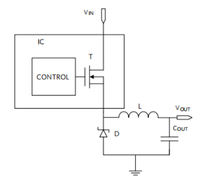 Figure 1. Asynchronous Buck Converter
In our example, the MOSFET RJK0651DPB features an Rds(on) of only 11 mΩ, with a package size similar to a Schottky rectifier. This results in a corresponding voltage drop of merely (11 mΩ) × (4 A) = 44 mV, and power loss of just (0.044 V) × (4 A) × (0.80) = 141 mW.
The MOSFET's power loss is approximately 14 times lower than the Schottky's power loss at full load! Clearly, the logical approach to minimize power consumption is to employ synchronous rectification.
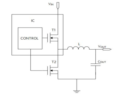 Figure 2. Synchronous Buck Converter
To minimize the overall size of the power supply circuit, newer synchronous rectification integrated circuits should incorporate internal compensation for any frequency and output voltage without requiring a large output capacitor. They should also operate at high frequencies to permit the use of smaller inductors and capacitors.
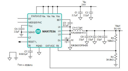 Figure 3. Typical Application Circuit for the MAX17536 24VIN/5VOUT, 4A Synchronous Rectifier Buck Converter
The MAX17536 and an asynchronous solution based on published specifications are shown in Figure 4. For both devices, test conditions were 24V input and 5V, 4A output. As expected, Maxim's synchronous solution demonstrated higher efficiency across the entire load current range. At full load (4A), Maxim's synchronous solution achieved over 92% efficiency, while the asynchronous device reached only about 86%, representing an efficiency difference exceeding 6%.
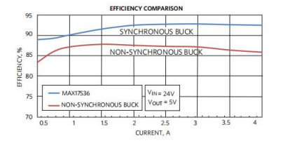 Figure 4. Efficiency of Synchronous and Asynchronous Buck Converters
Conclusion
When addressing power consumption challenges in industrial applications, the MAX17536 presents a synchronous rectification solution for high input voltages. This synchronous approach demonstrates a significant efficiency advantage, alleviating power dissipation concerns.