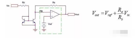
In many applications, such as battery chargers, solar controllers, etc., controlling the power supply is an essential task. The industry offers many off-the-shelf integrated power supplies; unfortunately, they do not provide an easy way to control the output. Typically, power supplies can be designed as power operational amplifiers with in-phase inputs connected to a reference voltage (in the green rectangle in Figure 1).
 Figure 1 This is a feedback stabilized power supply scheme.
Typically, the only channel in a power supply IC (i.e., TI's SimpleSwitcher) where you need to change Vout is the inverting pin that controls the feedback (FB in Figure 1). A very simple way to control FB is to replace Rb with a controlled current source, and the easiest and cheapest way to do this is to use a current mirror (Figure 2).
 Figure 2 This voltage controlled power supply uses a current mirror
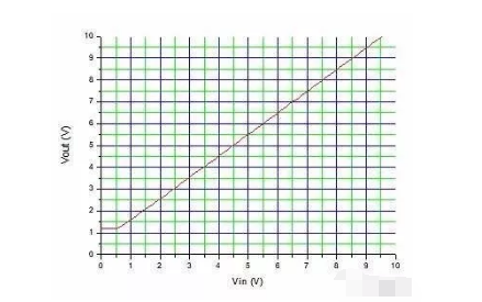
The accuracy obtained with this design is related to the accuracy of the current reflector that will be used. If you decide to use Widlar's basic two-transistor design, you must rely on intentionally manufactured matched pairs such as the BCV61. It is easy to use such components in the better performing Wilson4 transistor current mirrors. The current mirror only begins to operate when Vin exceeds the VBE(on) of the mirror transistor, hence the nonlinearity at the start. If the proposed design is part of a loop then all this is not very limited and feedback can compensate for the error through feedback magic.
Figure 3 shows the P-Spice analog scaling for the circuit of Figure 2 with Vref = 1.2V when Vin is between 0 and 10V.
 Figure 3 This figure shows the P-Spice analog scale of the circuit in Figure 2
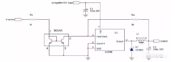
A direct realization of the principle shown in Fig. 2 is shown in Fig. 4. Here, the well known LM2596 is controlled by the off-the-shelf current mirror BCV61.
 Figure 4 This is a "work as designed" application of the principle of Figure 2.
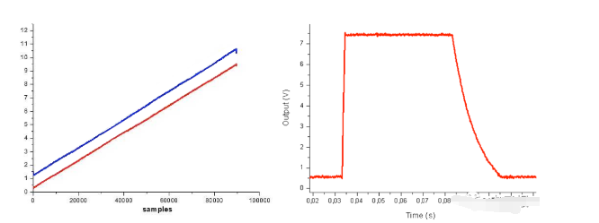
The prototype of Fig. 4 has been tested for linearity by connecting the unregulated DC input to a 22V supply, connecting the V control to a sawtooth wave generator spanning 0-10V@5Hz, and sampling the output (loaded with a 50Ω resistor) with an oscilloscope. A pulse generator (0-8V, 0.5s) has been used to check the time response.

The results are shown in Figure 5. The circuit has good linearity (left panel) and has a fairly fast transient response in terms of rise time (it takes about 1ms to reach the stabilization point). The fall time is related to the output capacitor (220µF) and the load (50Ω during testing).
Figure 5 These test results for the circuit of Figure 4 show the drive voltage (blue trace) and output (red trace on the left). On the right, the response to the square wave indicates a rise time of 1ms associated with the output capacitor and load resistance, with a slow fall time.


