Industrial motion control covers a wide range of applications, from inverter-based fan or pump control, to factory automation with more sophisticated AC drive controls, to advanced automation applications such as robotics with complex servo controls. These systems require detection and feedback of many variables such as motor winding current or voltage, DC bus current or voltage, rotor position and speed. The selection of variables and the required measurement accuracy depends on the end-application requirements, system architecture, target system cost or system complexity, and other considerations such as value-added features like condition monitoring. With motors reportedly consuming 40% of the world's energy, international regulations have increased the focus on system efficiency across industrial motion applications, increasing the importance of these variables, especially current and voltage.
This paper focuses on current and voltage detection in various motor control signal chain topologies based on motor power ratings, system performance requirements, and end applications. In this case, the motor control signal chain implementation varies depending on sensor selection, current isolation requirements, analog-to-digital converter (ADC) selection, system integration, and system power and ground partitioning.
Range of Industrial Drive Applications
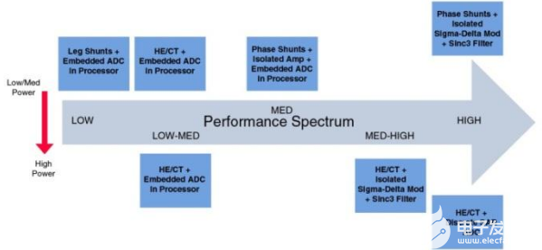
Motor control applications range from simple inverters to complex servo drives, but all include motor control systems with power stages and processors that drive pulse width modulator (PWM) modules with varying levels of detection and feedback. A simplified view of the range of applications is shown in Figure 1, illustrating systems that become increasingly complex as one moves from left to right, from simple control systems such as pumps, fans, and compressors, to systems that can be implemented without the need for precise feedback, using only simple microprocessors. As system complexity increases toward the higher end of the spectrum, complex control systems require precise feedback and fast communication interfaces. Examples include sensor or sensorless vector control of induction or permanent magnet motors, as well as high-power industrial drives designed for efficiency - such as the large pumps, fans and compressors shown in Figure 1. At the top end of the spectrum, sophisticated servo drives are used in applications such as robotics, machine tools, and pick-and-place machines. As systems become more complex, sensing and feedback of variables becomes more important.

Figure 1.Range of industrial drive applications.
Drive Architecture - System Partitioning
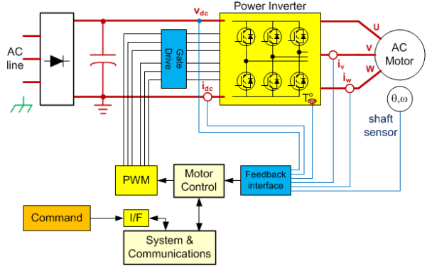
There are many challenges in designing systems to address a wide range of applications in industrial motion control. The general purpose motor control signal chain is shown in Figure 2.

Figure 2. Generalized motor control signal chain
The key issue is isolation requirements, which often have a significant impact on the final circuit topology and architecture. There are two key factors to consider: why isolate and where isolate.
The classification of isolation required will be determined by the former. Requirements can be high-voltage safety isolation (SELV) to protect against man-made electric shock, or functional isolation for level shifting between non-lethal voltages, or isolation for data integrity and noise mitigation purposes. The location of the isolation is usually determined by the expected system performance. Motor control is typically a harsh electrically noisy environment, and designs typically encounter large common-mode voltages of several hundred volts, possibly switching at frequencies in excess of 20 kHz, with very high transient dv/dt rise times. For this reason, it is common to isolate the power stage from the control stage, both in high performance systems and in systems where high power is inherently noisy. Whether the design utilizes a single-processor or dual-processor approach also affects the isolation location. In lower performance systems with lower power consumption, isolation is usually at the digital communication interface, which means that the power and control stages have the same potential. Low-end systems have lower bandwidth communication interfaces for isolation. Traditionally, isolating communication interfaces in high-end systems has been challenging due to the high bandwidth and limitations required by traditional isolation techniques, but this is changing with the advent of magnetically isolated CAN and RS-485 transceiver products.
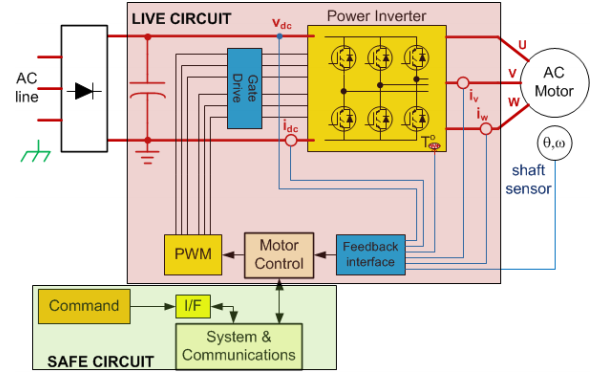
Two key elements in a high-performance closed-loop motor control design are the PWM modulator output and motor phase current feedback. Figures 3a and 3b illustrate where safe isolation is required, depending on whether the control stage shares the same potential as the power stage or is referenced to ground. In either case, isolation of the high end gate driver and current detection nodes is required, but at different levels of isolation - in Figure 3a, only functional isolation of these nodes is required, whereas in Figure 3b, physical safety (i.e. current) isolation of these nodes is critical.

Figure 3a. Control stage with power stage as reference
Measurement Techniques and Topologies for Current and Voltage Detection
Signal chain implementations for current and voltage detection vary depending on transducer selection, current isolation requirements, ADC selection and system integration, as well as system power and ground partitioning, as described earlier. Realizing signal conditioning for high-fidelity measurements is no easy task. For example, recovering small signals or transmitting digital signals in such noisy environments is challenging, while isolating analog signals is even more challenging. In many cases, signal isolation circuits introduce phase delays that can limit system dynamic performance. Phase current detection is particularly challenging because this node is connected to the same circuit node as the gate driver outputs within the center of the power stage (inverter module) and therefore has the same requirements in terms of isolating voltage and switching transients. Determining the measurement signal chain (technology, signal conditioning and ADC) to be implemented in the motor control system depends on three key factors:
The point or node in the system, as this determines what needs to be measured.
The power level of the motor and the resulting sensor selection - whether it is inherently isolated or not. The choice of sensor has a significant impact on the choice of ADC, including converter architecture, functionality and analog input range.
The end application. This may drive the need for high resolution, high accuracy, or speed in the detection signal chain. For example, implementing sensorless control over a wider speed range requires more measurements more frequently and higher accuracy. The end application also influences the need for ADC functionality. For example, multi-axis control may require a higher channel count ADC.
Current and Voltage Sensors
The most common current sensors used in motor control are shunt resistors, Hall effect (HE) sensors, and current transformers (CTs). Although shunt resistors do not provide isolation and incur losses at higher currents, they are the most linear of all sensors, have the lowest cost, and are suitable for both AC and DC measurements. The reduced signal level required to limit shunt power losses typically limits shunt applications to 50 A or less. CT and HE sensors provide inherent isolation that allows them to serve high current systems, but because the sensors themselves have poor initial accuracy or poor accuracy over temperature ranges, they are more costly and result in a solution that is less accurate than that which can be achieved with a shunt resistor .
Motor Current Measurement Locations and Topologies
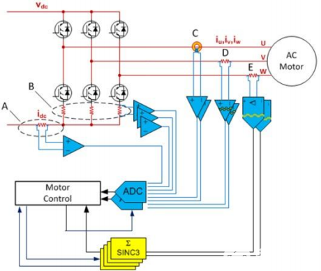
In addition to the sensor type, several motor current measurement nodes are available. The average DC bus current can be used for control purposes, but in more advanced drives, the motor winding current is used as the main feedback variable. Direct phase winding current measurement is ideal for high performance systems. However, winding currents can be measured indirectly using shunts in each lower inverter branch or a single shunt in the DC bus. These methods have the advantage that the shunt signals are all referenced to the power supply common, but extracting the winding current from the DC link requires synchronizing the samples to the PWM switches. Direct phase winding current measurements can be made using any of the above current detection techniques, but the shunt resistance signal must be isolated. A high common-mode amplifier can provide functional isolation, but human safety isolation must be provided by an isolation amplifier or isolation modulator.
Figure 4 shows the various current feedback options described above. Although only one of these options is required for control feedback, the DC bus current signal can be used as a backup signal for protection.

Fig. 4. Isolated and non-isolated motor current feedback
As mentioned earlier, system power and ground partitioning will determine the required isolation classification and thus which feedback options are appropriate. The system target performance will also affect the choice of sensor or measurement technique. There are many configurations that can be realized within the performance range.
Example of lower performance: power and control stages on common potential, detection options A or B
Using leg shunts is one of the most economical techniques to measure motor current. In this example, where the power stage shares the same potential as the control stage, there is no common mode to be dealt with and the outputs from option A or B can connect directly to the signal conditioning circuitry and ADC. This type of topology would generally be found in a low power and low performance system with the ADC embedded in the microprocessor.
Higher Performance Example: Control Stage Connected to Earth, Sensing Option C, D, or E
In this example, human safety isolation is required. Sensing options C, D, and E are all possible. Option E provides the highest quality current feedback of all three options and, being a higher performance system, it is likely that there is an FPGA or other form of processing in the system that can provide the digital filter for the isolated modulator signal. The ADC choice for option C, the isolated sensor (likely closed loop HE), would traditionally be discrete to achieve higher performance than that possible with embedded ADC offerings to date. Option D is an isolated amplifier in this configuration, vs.a common-mode amplifier, as safety isolation is required. An isolated amplifier will limit performance, and so an embedded ADC solution may suffice. This will provide the lowest fidelity current feedback compared to options C or E, and while an embedded ADC may be perceived as "free"and the isolated amplifier potentially "cheap," the implementation usually requires additional components for offset compensation and level shifting for ADC input range matching, increasing the overall signal chain cost.
There are many topologies that can be used in motor control design to sense motor current with many factors to consider such as cost, power level, and performance level. A key objective for most system designers is to improve the current sense feedback in order to improve efficiency within their cost targets. For higher end applications, current feedback is critical to other system performance measures such as dynamic response, acoustic noise, or torque ripple, not just efficiency. It is evident that there is a continuum of performance running from low to high across the various topologies available and this is coarsely mapped out in Figure 5 illustrating both lower power and higher power options.

Figure 5. current detection topology performance range
Goals, Needs and Resulting Trends for Motor Control System Designers: Migrating from HE Sensors to Shunt Resistors
Shunt resistors coupled to isolated sigma-delta modulators provide the highest quality current feedback where the current level is low enough for shunt use. There is a significant trend among system designers to migrate from HE sensors to shunt resistors, and another trend to move to an isolated modulator approach rather than an isolated amplifier approach. Replacing only the sensor reduces bill of materials (BOM) and PCB insertion costs and improves sensor accuracy. Shunt resistors are not sensitive to magnetic fields or mechanical vibration. Often, system designers replacing HE sensors with shunt resistors may choose an isolation amplifier and continue to use the ADC previously used in HE sensor-based designs to limit the level of variation in the signal chain. However, as mentioned earlier, the performance of the isolation amplifier will be limited regardless of the ADC performance.
Further replacing the isolation amplifier and ADC with an isolated sigma-delta modulator will eliminate the performance bottleneck and greatly improve the design, typically changing it from 9- to 10-bit quality feedback to 12-bit levels. Analog overcurrent protection (OCP) circuits can also be eliminated, as the digital filters required to process the sigma-delta modulator outputs can also be configured to enable fast OCP loops. Therefore, any BOM analysis should include not only the isolation amplifiers, the raw ADCs, and the signal conditioning between them, but also the OCP devices that may be eliminated.The AD7401A isolated Σ-Δ modulator is based on ADI coupler technology and has a differential input range of ±250 mV (±320 mV full scale typically used for OCP), which is well suited for resistive shunt measurements. The analog inputs are continuously sampled by the analog modulator and the input information is contained in the digital output stream at a density of up to 20 MHz data rate. The raw information can be reconstructed with an appropriate digital filter, typically a Sinc.®3 for precision current measurements. Since conversion performance can be traded off against bandwidth or filter bank delay, coarser, faster filters can provide fast response OCPs on the order of 2 μs, ideal for IGBT protection.
Shunt Resistor Size Reduction Required
From the signal measurement side, there are some key challenges in shunt resistor selection, as there is a trade-off between sensitivity and power consumption. Larger resistor values will ensure that the full range of the sigma-delta modulator or as much of the analog input range as possible is used, thus maximizing dynamic range. However, larger resistor values will also result in voltage drop and reduced efficiency due to the × R loss of the I2 resistor. Achieving nonlinearity through self-heating effects can also be a challenge when using larger resistors. As a result, system designers are faced with trade-offs, which are further exacerbated by the common need to select shunt sizes that can serve many models and motors at different current levels. Maintaining dynamic range is also challenging in the face of peak currents that can be several times the motor's rated current and the need to reliably capture both. The ability to control peak current when the system is turned on varies by design, from tightly controlled (e.g., 30% above nominal) to as much as 10 times nominal. Peak currents are also caused by acceleration and load or torque variations. However, in drive designs, peak currents in a system are typically four times the nominal current.
Faced with these challenges, system designers are looking for superior sigma-delta modulators with wider dynamic range or improved signal-to-noise and distortion ratio (SINAD). To date, isolated Σ-Δ modulator products have offered guaranteed performance with 16-bit resolution and up to 12 effective bits (ENOB).
SINAD = (6.02 N+ 1.76) dB where N= ENOB
With the move to shunt resistors in low-power drivers, motor driver manufacturers are also looking to increase the power rating of their drivers, a topology that can be used for performance and cost reasons. This can only be accomplished by using much smaller shunt resistors, which requires the emergence of higher-performance modulator cores to resolve the reduced signal amplitude.
System designers, especially servo designers, are also continually seeking to improve system response by reducing analog-to-digital conversion times or by reducing group delay through digital filters associated with isolated sigma-delta modulator and shunt resistor topologies. As mentioned earlier, conversion performance can be traded off against bandwidth or filter group delay. Coarser, faster filters can provide faster response, but at the expense of performance. The system designer analyzes the impact of filter length or extraction rate and then makes tradeoffs based on the needs of his or her final application. Increasing the clock rate of the modulator would help, but many designers already operate at the 20 MHz maximum clock rate acceptable for the AD7401A. One of the disadvantages of increasing the clock rate is the potential for radiation and interference (EMI) effects. A higher-performance modulator at the same clock rate will improve the group delay versus performance tradeoff, resulting in shorter response times while minimizing the impact on performance.


