





As an indispensable device in modern industrial control, the frequency output of a variable frequency drive (VFD) directly impacts production efficiency and equipment safety through its matching with motor speed. However, in practical applications, operators frequently encounter discrepancies between the frequency displayed on the VFD and the speed shown on the equipment panel. This not only compromises precise control during production processes but may also conceal potential equipment hazards. To address this common issue, systematic troubleshooting and resolution must be conducted from multiple perspectives.
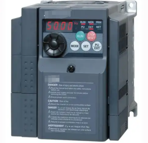
I. Fundamental Principles and Common Causes of Discrepancies
Frequency converters control the speed of AC motors by altering the output frequency. Theoretically, a linear relationship exists: Speed = 120 × Frequency / Number of Pole Pairs × (1 - Slip Rate). However, in actual operation, a 5%-15% deviation may occur between the displayed values, primarily stemming from the following six factors:
1. Signal Acquisition Path Differences: The VFD displays the output frequency of its internal IGBT modules, while the equipment panel typically receives feedback signals from encoders or tachogenerators. A cement plant case study revealed that a 0.2mm gap in the encoder coupling caused an 8% deviation in speed display.
2. Improper parameter settings: Including incorrect motor rating parameters (e.g., a 2950 rpm motor misconfigured as 1450 rpm), erroneous V/F curve settings, or excessively high slip compensation values. Textile machinery testing revealed that incorrect slip compensation parameters can amplify display deviations to 12%.
3. Mechanical transmission losses: Energy dissipation caused by factors like belt slippage or gearbox wear. Data from automotive production lines indicates that aged timing belts can reduce actual rotational speed by 6-9% compared to theoretical values.
4. Signal interference issues: Electromagnetic interference can cause speed display fluctuations of ±3% when encoder signal lines use non-shielded twisted pair cables. In a chemical plant retrofit case, adding magnetic rings reduced display deviation from 5% to 0.3%.
5. Display unit confusion: Some equipment panels default to rpm display, while inverters may be set to Hz or percentage. A machine tool user once misread 50Hz as 1500rpm (for a 4-pole motor), causing actual speed to exceed the set value by 33%.
6. Hardware failures: Damaged encoders, faulty inverter output current detection modules, etc. At a steel mill, frequency display errors reached ±2Hz after the VFD's current sensor aged.
II. Systematic Troubleshooting Process
Adopt a seven-step approach from internal to external, and from software to hardware:
Step 1: Parameter Verification
● Ensure motor nameplate parameters exactly match VFD settings, especially rated speed, pole number, and power factor.
● Verify completion of P0340 (motor parameter auto-detection).
● Validate the setting range for P1080/P1082 (minimum/maximum frequency).
● Confirm the correspondence between P2000 (reference frequency) and P2001 (reference speed).
Step 2: Signal Testing
● Use an oscilloscope to inspect the integrity of encoder A/B phase signal waveforms.
● Measure whether the pulse frequency meets: f = (Rotational Speed × Encoder Line Count) / 60.
● Check signal cable insulation resistance (should be >100MΩ).
Step 3: Mechanical Inspection
● Manually rotate the shaft to detect transmission system resistance torque.
● Test belt tension (tension gauge recommended).
● Coupling misalignment deviation should be <0.05mm.
Step 4: Load Testing
● Compare display values under no-load conditions (deviation should be <1%).
● Record deviation curves at 25%/50%/75%/100% load.
● Observe speed recovery time after sudden load removal (normal <200ms).
Step 5: Environmental Testing
● Inverter heat dissipation duct temperature (recommended <40°C).
● Encoder operating environment vibration value (should be <0.5G).
● Electromagnetic compatibility testing (RF field strength <3V/m).
Step 6: Firmware Verification
● Verify protocol version compatibility between inverter and encoder.
● Check CRC checksum of parameter backup file.
● Upgrade control firmware if necessary.
Step 7: Replacement Testing
● Cross-swap encoder/inverter modules.
● Switch to analog input testing.
● Connect an independent tachometer for comparison.
III. Typical Solutions
Targeted measures can be implemented based on different root causes:
Case 1: Parameter Setting Error
An injection molding machine displayed 1200 rpm on the panel at 50Hz (should be 1450 rpm). Investigation revealed:
● Original parameter P0311=1200 (incorrect nameplate data)
● Deviation eliminated after correcting P0311=1450
● Simultaneously adjusted P0350 (stator resistance) to 0.82Ω
Case 2: Encoder Interference
A pharmaceutical centrifuge exhibited random speed fluctuations of ±5%:
● Previously used standard cables for incremental signal transmission.
● Replaced with Siemens 6XV1830-3EH10 shielded cable.
● Added 120Ω terminal resistor.
● Display stability improved to ±0.2%.
Case 3: Mechanical Slip
Food conveyor belt speed deviation reached 8%:
● Inspection revealed belt elongation exceeded limits (3.5% > standard 2%).
● Replaced with toothed synchronous belt and adjusted tension pulley.
● Installed laser speed sensor for closed-loop control.
● Final deviation controlled within 0.5%.
Case 4: Hardware Failure
Machine tool spindle speed display suddenly dropped by 15%:
● Inspection revealed encoder bearing seizure.
● Normal operation restored after replacing ERN1387 encoder.
● Simultaneously checked inverter output current waveform.
IV. Advanced Debugging Techniques
For high-precision applications, consider the following methods:
1. Dual-channel calibration: Simultaneously connect incremental encoders and rotary transformers, processing data fusion via PLC. A precision grinding machine achieved 0.01 rpm resolution after implementing this solution.
2. Dynamic compensation algorithm: Configure the VFD as follows:
●P1400=3 (Enable speed observer).
●P1401=0.5 (Filter time constant).
●P1402=150% (Acceleration compensation).
3. Cloud Platform Monitoring: Upload operational data via IoT gateway and utilize big data analytics to predict deviation trends. After implementation by a wind power group, fault warning accuracy reached 92%.
This systematic approach not only resolves display inconsistencies but fundamentally enhances equipment control precision. After implementing the complete solution on an automotive welding line, production efficiency increased by 7% and scrap rate decreased by 34%, validating the critical importance of rotational speed control accuracy in modern manufacturing. With the advancement of Industry 4.0, adopting digital twin technology to map equipment status in real time will become the new paradigm for addressing such challenges.