


CAN (ControllerAreaNetwork) bus, i.e. Controller Area Network bus, has been widely used in industrial control, medical electronics, household appliances and sensor fields. At present, domestic and foreign literature for the CAN bus protocol analysis of the article is mainly for the CAN protocol frame structure to or bit timing characteristics of the analysis, such as the literature is rarely from the perspective of communication on the CAN bus protocol analysis, rarely from the perspective of engineering applications, the CAN bus communication mechanism for in-depth analysis of the article.
1. CAN application characteristics and structural composition
The CAN bus protocol has two international standards, ISO11898 and ISO11519, of which, IS011898 is a high-speed CAN communication standard with a communication rate of 125kbps to 1Mbps, which is a closed-loop bus with a maximum length of 40m/1Mbps. ISO11519 defines a low-speed CAN communication standard with a communication rate of 10 to 125kbps, which is a low-speed CAN communication standard with a maximum length of 40m/1Mbps. ISO11519 defines the communication rate of 10 to 125kbps low-speed CAN communication standard, belongs to the open-loop bus, the maximum length of 1km / 40kbps. due to the electrical characteristics of the limitations, that is, the bus distribution of capacitance and distribution of resistance on the bus waveform, the maximum number of nodes on the CAN bus is 110. For the application engineer, only the baud rate and bit parameters of the transceiver side need to be correctly configured to achieve data synchronization of the transceiver nodes. Through the CAN controller hardware on the message marker filtering can be realized point-to-point, point-to-multipoint and global broadcast and other ways to transmit and receive data. At the same time, due to the short frame structure of CAN telegrams, and each frame contains a CRC check part, which ensures a very low data error rate.
The CAN application layer, the operating system (implemented as a background program in applications without an operating system) and the driver in the system implementation together realize the application layer functions in the ISO reference model. Among them, the CAN application layer defines ID grouping, sending data loading, receiving data processing, and application layer bus security monitoring; the operating system/background program is used to schedule the CAN driver to process the data after the CAN interrupt arrives; the driver includes initialization (controller working state setting, baud rate setting, acceptance filter configuration), transceiver driver, and abnormality handling program.
For the transmission medium layer, it needs to be determined according to the environmental interference noise, bus length and so on. In the case of strong interference noise must be used shielded wire; due to the distribution of capacitance caused by the bus waveform distortion and distribution of resistance caused by the attenuation of the bus level, the length of the bus needs to take into account the distribution of resistance and capacitance characteristics of the transmission medium used; at the same time, if the use of high-speed bus also need to experiment to determine the value of the matching resistance of the bus.
For the realization of CAN controller, you can choose the CAN controller integrated in the system master chip, such as NXP's LPC2000 series of microcontrollers, or you can also use discrete components of the CAN controller, such as the SJA1000 For the realization of CAN transceivers, you can choose the CTM1050, TJA1050, etc. If the ambient interference noise is large, you need to consider the transmission medium distribution resistance and distribution capacitance characteristics; at the same time, if you use a high-speed bus also need to determine the matching resistance of the bus through experimentation. If the environmental interference noise is large, it is necessary to add an isolation chip between the controller and the transceiver or the use of integrated isolation function of the CAN transceiver. It is worth mentioning that NXP's new LPC11C24 microcontroller chip not only integrates a CAN controller, but also integrates a CAN transceiver function, which provides good support for the rapid development of CAN bus systems. In addition, according to the actual application of the length of the bus and the number of nodes on the bus, it is also necessary to consider the delay time of the transceiver chip's transmission and reception.
For the CAN driver layer and application layer, the driver includes CAN initialization (including hardware enable, baud rate setting, controller operating mode setting and acceptance filter ID table configuration), receive/transmit driver and provides interface functions to the upper layer, of which it is necessary to explain that the acceptance filter ID table configuration needs to be based on the grouping of the system ID by the application layer; the CAN application layer performs data packetization based on the data sending/receiving relationship between the nodes on the bus. CAN application layer according to the data sending and receiving relationship between the nodes on the bus for packet ID grouping, sending data packets, receiving data processing and application layer bus security monitoring. In addition, the commonly used CAN bus upper layer protocols include CANOpen, DeviceNet and iCAN.
2. CAN bus synchronization mechanism analysis
In the communication process, one of the most important issues to be resolved is how to achieve the synchronization of data at the sender and receiver ends, i.e., the receiver end can correctly receive and parse the data sent by the sender end.CAN bus protocol is a kind of asynchronous serial communication protocol, which belongs to the baseband communication, and its synchronization is realized from the high-level data link control protocol (HDLC). Specifically, the synchronization of the CAN bus protocol is achieved through 3 aspects as described below.
2.1 Parameter setting
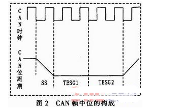
Both sides of the communication through the software set the same baud rate, the same phase adjustment segment length, the same synchronization jump width, through the above three elements set, defines the length of the bit time in the transmission process of the CAN bus as well as the location of the sampling point, the bit structure as shown in Fig. 2, the CAN clock in the figure that is defined in the protocol of the TQ time, which is obtained through the frequency division of an external clock or a peripheral clock of the CPU. The basic clock signal of the CAN controller is obtained by dividing the frequency of the external clock or the CPU peripheral clock. The SS segment corresponds to the start segment, and the hopping edge on the bus should occur during this period, TESG1 corresponds to the transmission segment and the phase adjustment segment 1, and TESG2 corresponds to the phase adjustment segment 2, and for the high-speed bus, the controller samples and discriminates the bus between TESG1 and TESG2.
2.2 Fixed frame structure
CAN protocol clearly defines a fixed frame structure to facilitate the CAN controller and transceiver to monitor the bus state, in the CAN2.0 protocol specification, divided into standard frame and extended frame two frame structures, the difference lies only in the arbitration domain, the standard frame using 11-bit identifier, while the extended frame has a 29-bit identifier, the specific standard frame, extended frame frame structure.
2.3.3 Hard Synchronization and Resynchronization
2.3.1 Hard Synchronization
The so-called hard synchronization means that during the bus idle period (i.e., the bus level is expressed as a continuous recessive bit), once the controller detects the jump from the recessive level to the dominant level, it means that at this time there is a station on the bus to start sending data, then force the bit state counter of the CAN controller to synchronize to the SS segment shown in Fig. 2, and at the same time, the bit clock starts to recount from this point onwards (the CAN bit time is set by the upper software layer). Hard synchronization is used for the start of frame determination.
2.3.2 Resynchronization
In the CAN bus protocol, resynchronization is implemented based on the bit-filling mechanism. Similar to the HDLC protocol, in the frame structure of CAN, once five consecutive bits of the same polarity are detected from the start of the frame until the CRC sequence bit, the CAN controller automatically inserts a bit of the opposite polarity. Re-synchronization is that during data transmission, the CAN controller adjusts the phase adjustment segment 1 and phase adjustment segment 2 by detecting the difference between the hopping edge on the bus and the node's internal bit time, and the adjustment size is programmed by the synchronization hopping width, and the adjustment size is set in TQ. The specific adjustment rule is that, in the transmission process, the hopping edge on the bus detected by the CAN controller is adjusted by the CAN controller if it is located within the node's internal SS bit time period, then no adjustment is required; if the skip edge is located in the TESG1 segment, it means that there is a delay in the bit time on the bus relative to the bit time of the node, then the CAN controller extends the TESG1 bit time period of the node, and if the value of the delay time (the value of T0) is greater than the synchronization skip width, the extension time is the synchronization skip width value, otherwise the CAN controller of the node extends the difference between it and the bit time of the bus; if the The jump edge is located in the TESG2 segment, indicating that the bit time on the bus is overrun relative to the bit time of the node, then the CAN controller reduces the node's TESG2 bit time period, the specific adjustment rules are similar to those of the TESG1 segment.
3. CAN bus address mechanism analysis
Unlike industrial Ethernet, RS485 and other buses, the CAN bus sends and receives data through the packet ID rather than the node address, i.e., the nodes on the CAN bus do not have a fixed address, instead, each node needs to be configured through software with an ID table (in the acceptance filter unit of the node), and if the ID number of the data packet on the bus exists in the ID table of the node, then the The packet successfully passes the acceptance of the acceptance filter unit of that node and will be sent to the upper software processing unit and processed accordingly, otherwise, the packet is discarded. For example, if node A on the bus wants to send a packet to node B, the ID number of the packet must be located in the ID table of node B. Similarly, if node A wants to broadcast a packet to the bus, the ID number of the packet must be located in the ID tables of all other nodes on the bus. As mentioned earlier, the ID table is configured through software, but the acceptance filtering function is performed through the acceptance filter, a hardware unit in the CAN controller, so the delay caused by acceptance is small in terms of speed. In addition, the advantage of using this address mechanism is that the system employing this bus is highly flexible, i.e., new nodes added or deleted do not affect the communication between the original nodes of the system.
The following will take the CAN controller integrated with NXP's LPC2478 chip as an example to specify the address configuration method of the CAN bus system. As shown in Figure 3, first classified according to the data packets to be transmitted on the bus, that is, the packet ID and the corresponding node planning, for example, in our system there are mainly the following types of packets: query packets, control command packets (including action and parameter packets), alarm packets and feedback parameter packets, corresponding to the node characteristics of the query packets and control command packets are mainly the master station sent to each slave unit, while alarm data packets and feedback parameter data packets are mainly sent from each node unit of the slave to the master unit node. Then, the acceptance filter unit of each node is configured according to the ID classification, and the specific configuration method is as follows: firstly, configure the corresponding acceptance filter working modes according to the node characteristics: the off mode (not receiving bus messages), the bypass mode (receiving all messages on the bus) and the normal working mode (hardware filtering). If the configuration for the normal mode of operation, then you need to configure the corresponding acceptance filter table (ID table), that is, the node needs to receive the packet ID number of the node controller to fill in the corresponding ID table area, and this completes the CAN bus node address allocation work. Generally speaking, the ID table is divided into the following four areas: clear standard frame identifier area, standard frame group format identifier area, clear extended frame format identifier area and extended frame group format identifier area. Among them, the explicit format is a single independent ID identifier, while the group format area has consecutively numbered ID identifiers.
4. CAN bus arbitration mechanism analysis
Bus arbitration, refers to when the bus has more than one node at the same time to send data bus protocol processing methods. CAN bus uses a non-destructive arbitration mechanism, that is, if more than one node on the bus at the same time to send data, with a high-priority packet node arbitration wins, you can continue to send data, and other arbitration failure node will exit the sending state and turn into a receiving node, with other bus arbitration mechanisms (such as the CSMA of LAN). (Compared with other bus arbitration mechanisms (e.g. CSMA/CD of LAN), it will not only not destroy the sent data, but also will not cause the delay of sending data, which is one of the advantages of CAN bus compared with other buses, and it is mainly realized by the following two features of CAN bus: 1) The line and characteristics of CAN bus, i.e., when more than one node on the bus sends dominant and invisible levels at the same time, the bus level is dominant level. 2) The line and characteristic of CAN bus, i.e., when more than one node on the bus sends dominant and invisible levels at the same time, the bus level shows the dominant level. 2) CAN controller is monitoring the bus level status even while sending data, i.e., when in arbitration, when the controller sends invisible level but detects the bus as visible level, the node arbitration fails and turns to the receiving node.
5. CAN bus robustness analysis
The robustness of CAN bus is realized through its real-time detection and monitoring of the node and bus packet security, in addition, CAN bus has a strong inhibition of external interference signals through the use of differential signals. Specifically discussed below.
5.1 Real-time monitoring of the bus waveform
CAN controller will not only monitor the data packets sent by other nodes on the bus all the time after powering up, but also monitor the data sent by itself in the process of sending data packets in real time, once the detection of errors in place, padding errors, CRC errors, formatting errors, or response errors, the node will be based on the state of the error in which it is (error activated or error recognized state) to send the corresponding error flag. In fact, I believe that only the error activation site sends the activation error logo (i.e., 6 consecutive dominant bits followed by 8 recessive bits of the error logo defining character) will have an impact on the bus and the nodes on the bus, while the node in the error recognition state sends the error recognition logo does not actually have any effect on the bus (the 6 recessive levels sent with the idle state of the bus is the same).
5.2 Real-time Monitoring of Node Status to Determine Node Privileges
Nodes change their state (error-activated, error-recognized, or bus-off state) in real time according to the packets sent on the bus. Nodes in error-activated state participate in bus communication normally, and error-recognized units participate in bus communication, but need to send 8 additional implicit bits before they initiate the next send. For packets sent on the bus, as shown in Table 1, the 15-bit CRC sequence implements the monitoring of the start bit, the arbitration field, the control field, and the data field (if any), the receiving site generates the CRC sequence of the packet according to the same algorithm as that of the sending node when it receives the data and compares it with the received CRC sequence, if it is different then it means that there is an error and the receiving node will not respond to the The receiving node will not respond to the packet, and the sending node will detect the response error and resend the packet. In conclusion, CAN bus has achieved high data security and bus stability through the data link layer and the physical layer.
6. Conclusion
Based on ISO11898 protocol specification, the paper analyzes in detail the realization principle and basis of CAN bus node synchronization mechanism, node address mechanism, bus arbitration mechanism (i.e. bus conflict resolution mechanism) and bus robustness from the perspective of communication, and at the same time briefly introduces the application characteristics of CAN bus and the system layered structure of the bus when it is applied to actual system, which is very important for the in-depth understanding of CAN bus protocol and the application of CAN bus to actual system. It is a guide for understanding the CAN bus protocol and applying the CAN bus to specific engineering projects, as well as researching or developing bus systems for specific requirements.