





Transmission mechanisms are key components in mechanical equipment that transmit power to achieve mechanical motion. When designing a transmission mechanism, the calculation of load inertia is crucial, as it directly affects the stability and reliability of the transmission mechanism. The following are the calculation methods and examples of load inertia for common transmission mechanisms:
I. Calculation Methods for Load Inertia of Common Transmission Mechanisms
1. Ball Screw Drive Mechanism
Ball screw drive mechanisms are widely used in precision positioning systems. The calculation of their load inertia needs to take into account factors such as load mass, screw lead, screw diameter and friction coefficient.
Assume the load mass is m, the screw lead is Pb, the screw diameter is Db, and the load moving speed is V. The load inertia converted to the motor shaft can be calculated by the following formula:
Load Inertia=4×π2×Motor Speed2m×Pb2
The motor speed needs to be converted according to the load moving speed and the screw lead. In addition, the inertia of the screw itself and the influence of friction loss on the system inertia should also be considered.
2. Timing Pulley Drive Mechanism
Timing pulley drive mechanisms are widely used in automation equipment due to their advantages of smooth transmission, low noise and high positioning accuracy. Their load inertia calculation includes the inertia of the timing pulleys and the inertia of the load.
Assume the diameter of the timing pulley is D and the load mass is M. The inertia of the timing pulley can be calculated by the following formula:
Timing Pulley Inertia=21×M×D2
The load inertia is calculated according to the mass and shape of the load, which is then added to the inertia of the timing pulley to obtain the total load inertia.
3. Gear Drive Mechanism
Gear drive mechanisms feature accurate transmission ratio, high efficiency and compact structure. The calculation of their load inertia needs to consider the inertia of the gear hub, the inertia of the gear shaft and the dynamic effects during gear meshing.
Assume the mass of the gear hub is m1 with a radius of r1, and the mass of the gear shaft is m2 with a radius of r2. The inertia of the gear hub is I1=m1×r12, and the inertia of the gear shaft is I2=m2×r22. The load inertia is calculated according to the mass and shape of the load, which is then added to the inertia of the gear hub and gear shaft to obtain the total load inertia.
In addition, the influence of factors such as friction loss, gear backlash and elastic deformation during gear meshing on the system inertia should also be taken into account.
4. Belt Drive Mechanism
Belt drive mechanisms have the advantages of smooth transmission, simple structure and convenient maintenance. Their load inertia calculation includes the inertia of the belt pulleys and the inertia of the belt.
The calculation method for the inertia of belt pulleys is similar to that of timing pulleys, while the inertia of the belt needs to be calculated based on factors such as the belt's material parameters, working conditions and length. Generally, the inertia of the belt is relatively small, but its influence cannot be ignored in high-speed transmission systems.
5. Chain Drive Mechanism
Chain drive mechanisms are characterized by high transmission efficiency, strong load-bearing capacity and adaptability to harsh environments. Their load inertia calculation includes the inertia of the sprockets and the inertia of the chain.
The calculation method for the inertia of sprockets is similar to that of gear hubs, while the inertia of the chain needs to be calculated based on factors such as the chain's material parameters, working conditions and length. Compared with belt drive, chain drive generally has a larger inertia, so its influence on the dynamic performance of the system must be fully considered in the design.
II. Case Analysis
Taking the ball screw mechanism in a servo drive system as an example, the load inertia calculation and motor selection are carried out as follows:
1. Known Conditions
- Load mass m=200 kg, screw lead Pb=20 mm, screw diameter Db=50 mm, screw mass mb=40 kg
- Friction coefficient μ=0.002, mechanical efficiency η=0.9
- Load moving speed V=30 m/min, total moving time t=1.4 s
- Acceleration/deceleration time t1=t3=0.2 s, dwell time t4=0.3 s
2. Calculation Process
- First, calculate the load inertia converted to the motor shaft, including the rotational inertia of the heavy load converted to the motor shaft and the rotational inertia of the screw, then obtain the total load inertia.
- Next, calculate the motor speed and the torque required for the motor to drive the load, including the torque required to overcome friction and the torque required for the acceleration of the heavy load and the screw, and finally obtain the maximum required torque.
3. Motor Selection
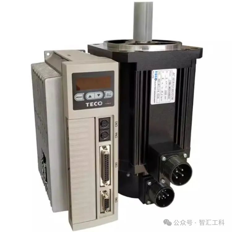
Based on the calculation results, the TECO JSDEP-20A series servo motor is selected, which has the following specifications that meet the design requirements:
Rated speed: 3000 RPM (adjustable to 2500 RPM for operation)
Rated torque: 12 N·m (satisfies the load torque requirement)
Rotor inertia: (close to the required value of
  , adaptable within the error range)
Load inertia ratio: 145/29≈5:1 (complies with the design criteria)
III. Conclusions
- In the design of transmission mechanisms, the load inertia must be calculated accurately to ensure the stability and reliability of the transmission mechanism.
- The calculation of load inertia needs to take into account various factors, including geometric parameters, material parameters and working conditions.
- For motor selection, factors such as load inertia, motor speed and required torque must be comprehensively considered to select the most suitable motor.
In summary, the calculation methods and case analysis of load inertia for common transmission mechanisms are of great significance for the design of transmission mechanisms and motor selection. Accurate calculation and rational selection can ensure the stability and reliability of transmission mechanisms and improve the performance of mechanical equipment.