





CAN bus (Controller Area Network) is a highly reliable, real-time serial communication protocol used in vehicles, industrial automation, and other fields. It enables multiple microcontrollers and devices to communicate with each other without a host computer.
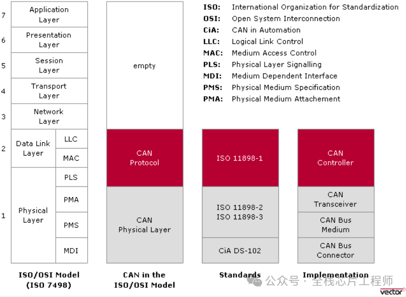
The CAN bus was originally developed by Bosch in Germany in the early 1980s for in-vehicle communication. In 1993, ISO published the CAN bus standard (ISO 11898), encompassing both the data link layer protocol and the physical layer protocol.
ISO 11898-1: Defines the data link layer protocol.
ISO 11898-2: Defines the physical layer protocol for high-speed CAN bus, supporting a maximum data transfer rate of 1 Mbps. It recommends a linear topology and is suitable for applications with high real-time requirements.
ISO 11898-3: Defines the physical layer protocol for low-speed CAN bus, with data transfer rates ranging from 40 Kbps to 125 Kbps. Also known as fault-tolerant CAN, it enables continued communication even when one signal line fails, making it suitable for applications with lower real-time requirements.
CAN Bus Features:
Multi-Master Control: The CAN bus supports multiple master devices coexisting on the network without a master-slave hierarchy. Devices communicate based on message priority.
Differential Signaling: Utilizes two wires (CAN_H and CAN_L) to transmit differential signals, enhancing resistance to electromagnetic interference.
Non-Destructive Arbitration: During message transmission, if a collision occurs, the higher-priority message is transmitted while the lower-priority message waits for retransmission.
Error Detection and Handling: Features robust error detection and handling capabilities, including CRC checksum verification and bit error checking.
Flexible Topology: Supports multiple network topologies such as linear, star, tree, and ring configurations.
On the CAN bus, the significant voltage difference between logic "0" and "1" ensures reliable communication. Referring to the description above, the two logic levels on the CAN bus are:
Dominant: 0
Recessive: 1
The signal levels on the CAN bus exhibit line-and characteristics. This line-and behavior forms the circuit basis for CAN bus arbitration: the dominant level (0) always masks the recessive level (1). If different nodes simultaneously transmit dominant and recessive levels, the bus exhibits the dominant level (0). Only when all nodes transmit the recessive level (1) does the bus exhibit the recessive state.
Dominant Level: Logic 0. In High-Speed CAN, the CAN_H pin drives to 5V, while the CAN_L pin drives to 0V.
Submissive Level: Logic 1. Neither pin is driven.
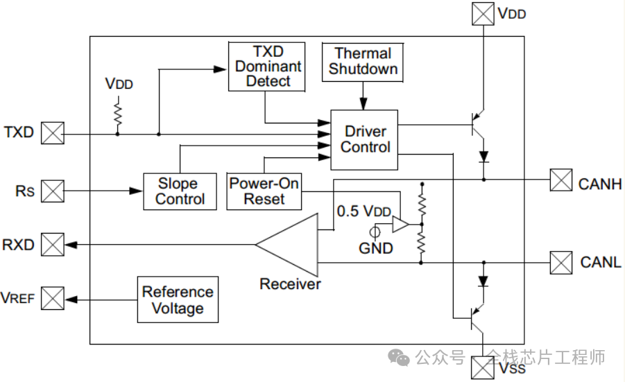
High-speed CAN and low-speed CAN buses differ in their physical layer signal level definitions:
High-speed CAN defines a logic "1" when CANH and CANL voltages are equal (CANH = CANL = 2.5V), and a logic "0" when the voltage difference between CANH and CANL is 2V (CANH = 3.5V, CANL = 1.5V).
Within the common-mode voltage range (-12V to 12V), the high-speed CAN transceiver interprets a voltage difference greater than 0.9V between CANH and CANL as the dominant state, and a difference less than 0.5V as the recessive state. An internal hysteresis circuit reduces interference.
Low-speed CAN defines a logic "1" when the voltage difference between CANH and CANL is 5V (CANH = 0V, CANL = 5V), and a logic "0" when the voltage difference is 2.2V (CANH = 3.6V, CANL = 1.4V).
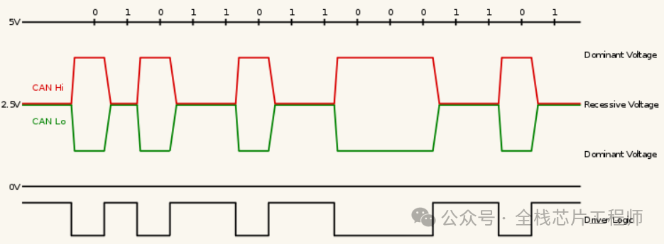 High-Speed CAN Signal Levels (ISO 11898-2)
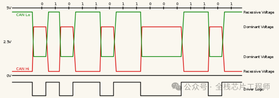 Low-Speed CAN Signal Levels (ISO 11898-3)
CAN Error Handling Mechanisms:
CRC Errors: Detects errors by calculating and verifying the CRC value of data.
Bit Errors: Detects bit errors in real-time during transmission.
Error Frames: Sends error frames to request retransmission when errors are detected.
Summary
CAN bus has gained widespread adoption across multiple fields due to its high reliability, real-time performance, and flexibility. As technology advances, CAN bus continues to evolve-for instance, the CAN FD (Flexible Data-Rate) standard released by BOSCH further enhances data transmission rates to meet the demands of applications requiring higher bandwidth.