The principle of motor control is the core of the field of motor technology, which involves the working principle of the motor, control methods and practical applications and other aspects. With the development of modern industry, the motor as an important device for energy conversion and transfer, its control accuracy and efficiency directly affect the performance and efficiency of the whole system. Therefore, an in-depth understanding and study of the motor control principle has important theoretical and practical significance.
First, the working principle of the motor
The motor is a device that converts electrical energy into mechanical energy, and its working principle is based on the law of electromagnetic induction and the law of electromagnetic force. According to its working principle, motor can be divided into two categories: DC motor and AC motor.
1. the working principle of DC motor
DC motor is the use of DC current flow through the armature coil and magnetic field coil interaction, generating torque to achieve mechanical movement of the device. Its main structure includes armature, magnetic poles, brushes and magnetic field. When DC current passes through the armature coil, it creates a magnetic field that interacts between the armature and the magnetic field, which generates a torque that starts the motor running. The speed of DC motor can be controlled by adjusting the armature voltage or armature current.
2. The working principle of AC motor
AC motor is a device that uses the constant change of AC current to generate a rotating magnetic field, thus realizing mechanical movement. According to the principle of generating rotating magnetic field, AC motor can be divided into asynchronous motor and synchronous motor two types. Asynchronous motors (also known as induction motors) are based on the principle of electromagnetic induction. When AC current passes through the stator windings, a rotating magnetic field is generated in the stator, and the rotor interacts with the rotating magnetic field due to the induction effect, thus generating a rotating torque to drive the motor. Synchronous motor is based on the motor speed and power supply frequency has a fixed proportional relationship between the motor to work, its speed and power supply frequency is strictly synchronized.
Second, motor control methods
Motor control methods mainly include speed control, starting control and braking control. These control methods and their principles are described in detail below.
1. speed control
Speed control is the most important and complex aspect of motor control. There are various speed control methods, including resistance voltage division speed control, frequency conversion speed control and vector control. Resistance voltage division speed control is a method to reduce the motor speed by changing the power supply voltage of the motor, this method is simple and easy to implement but less efficient. Frequency conversion speed control is a method to regulate the motor speed by changing the frequency of AC power supplied by the power supply, this method can realize a wide speed range and high efficiency. Vector control is a more advanced control method, which realizes the precise adjustment of motor speed and torque by precisely controlling the current and magnetic field of the motor, and is suitable for occasions with higher requirements on motor performance.
2. Starting control
Starting control is the control of the motor in the process from the stationary state to the running state. For asynchronous motors, due to its starting torque is small, so it is necessary to use some special methods to realize smooth starting. Common starting control methods include direct starting, reduced voltage starting and soft starting. Although direct starting is simple, but the starting current is large, and the impact on the power grid is large; reduced voltage starting is to reduce the starting current by reducing the supply voltage; soft starting is the use of power electronic devices to achieve smooth control of the motor starting process.
3. Braking control
Braking control is the control of the motor from the running state to the stationary state in the process. Brake control methods have a variety of methods, including energy braking, reverse braking and feed-back braking. Energy consumption braking is through the stator winding in the motor into the DC power to produce braking torque; reverse braking is by changing the motor power supply phase sequence to produce the opposite direction of rotation with the motor torque to achieve braking; feed-back braking is the use of the motor's generating characteristics of the mechanical energy will be converted into electrical energy and fed back into the grid to achieve braking.
Third, the motor control circuit diagram
1. permanent magnet motor control circuit diagram
This is the schematic diagram of the permanent magnet motor control circuit. This circuit is used to control the permanent magnet control. The circuit uses AC triac switching elements to enhance the commutation characteristics because permanent magnet motors are generators and standard triac switching elements are difficult to commute properly. Permanent magnet motors require full-wave DC rectification.
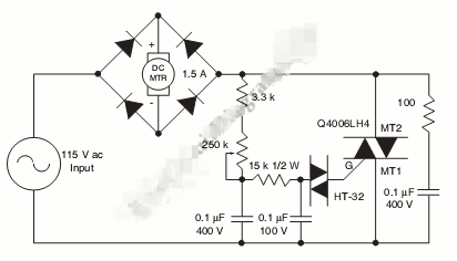
AC bidirectional thyristors are connected in series on the AC input side of the rectifier bridge. The most critical part of installing an SCR on the DC side of the bridge is dealing with delayed turn-on and timing near the end of the half-cycle. The circuit provides wide-range control so that the AC triac switching element can be triggered fast or with low conduction at low motors. The AC resistor and rectifier have similar voltage ratings. All are based on actual motor load and line voltage requirements.
2. 555 IC PWM Motor Control Circuit Diagram with Current Limiter
To provide fast motor speed changes and motor direction reversal, four outputs drive MOSFET H-bridges. The N-channel devices are lower rail power MOSFETs and the P-channel are upper rail power MOSFETs. they are all driven by the TC4469.
Small series resistors help prevent gate oscillations and slow the transition time of the lower rail device, which helps keep the upper device off. Resistor dividers and low-cost level-shifting transistors can be easily and economically added to maintain the 15VDC gate drive of the upper-rail MOSFET to achieve motor voltages in excess of 12VDC.
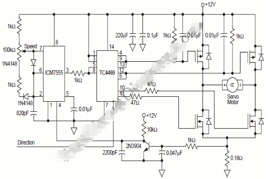
At voltages above 15VDC, a simple linear regulator can power them from a positive motor supply because the ICM7555 and TC4469 require negligible current. To help protect the gate from power transients, we can use a Zener diode. When the lower MOSFET in the same bridge arm is "on", a high dV/dT is generated and the gate-to-source capacitor helps keep the upper MOSFET "off". Another solution to this situation is to keep the gate drive impedance of the upper MOSFET low in the "OFF" state.
The sense resistor in the H-bridge ground pin provides a simple method of sensing motor current pulse by pulse, regardless of whether the motor is rotating forward or reverse. This signal is filtered and applied to the ICM7555 in order to inhibit PWM generation when the motor current exceeds the allowed value.
3. stepper motor control circuit diagram
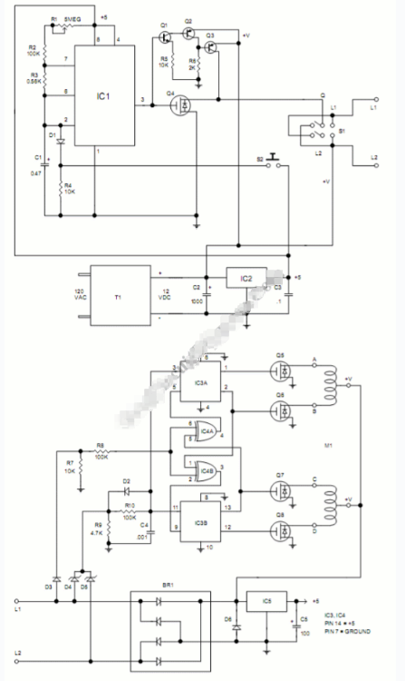
Stepper motors provide simple, low-cost and accurate position control. The stepper motor can be driven by a circuit mounted near the motor and controlled by a remote control circuit over a long cable. The circuit is interesting in that power to both the motor and the driver circuit is transmitted over two wires which also transmit the control signals.
LMC555 CMOS timer integrated circuit (IC1) generates 200 microsecond pulse to stepper motor and control its speed. The speed of the motor can be changed by varying the frequency of this pulse and a R1 variable resistor is provided for this purpose. At the output of IC1 (pin 3), a negative clock pulse drives the gate of the IRL530N (Q1) power FET, which immediately closes and disconnects the driver board from ground. This power interruption sends a signal to the motor driver to step the motor. The direction of rotation is controlled by the polarity of the voltage applied to the driver circuitry through interconnects L1 and L2.
MPSA05 bipolar NPN transistor Q2 and MPSA55 PNP transistors Q3 and Q4 invert the pulses from pin 3, pulling the drain of Q1 high when Q1 is turned off. Toggle switch S1 sets its direction by switching polarity. Pushbutton S2 starts and stops the motor by turning the clock on and off.
4. PWM Motor Control Circuit Diagram with Forward, Reverse and Brake Operation
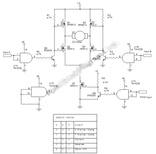
This PWM motor control circuit provides a variety of controls for a DC motor. You can control a DC motor to forward, reverse, or brake until it stops.
The circuit uses a MOSFETS bridge to drive the motor, controlled by a number of logic gates and small bipolar transistors. The motor voltage can be 10-20 volts and the current should be 8 amps maximum. The MOSFETs should be fitted with appropriate heat sinks. The V+ input should be powered by the DC motor operating voltage (10-20 volts). Although the MOSFET is designed for 100 volt operation, you can only use a maximum of 20 volts because this voltage is also used to drive the gate, which is normally limited to 20 volts. The minimum value for this supply voltage is 10 volts because the gate will not fully open if the voltage falls below 10 volts. You can choose from several types of 10-20 volt DC motors for this application.