


In industrial automation control systems, encoders serve as critical position feedback components, with their accuracy directly impacting equipment performance. Errors in mechanical position (MPOS) and digital position (DPOS) are common in servo systems, particularly in scenarios requiring high synchronization. Such deviations may lead to equipment vibration, positioning inaccuracies, or even production accidents. This paper systematically outlines the practical approach to addressing this technical challenge, covering error analysis, troubleshooting methods, and solutions.
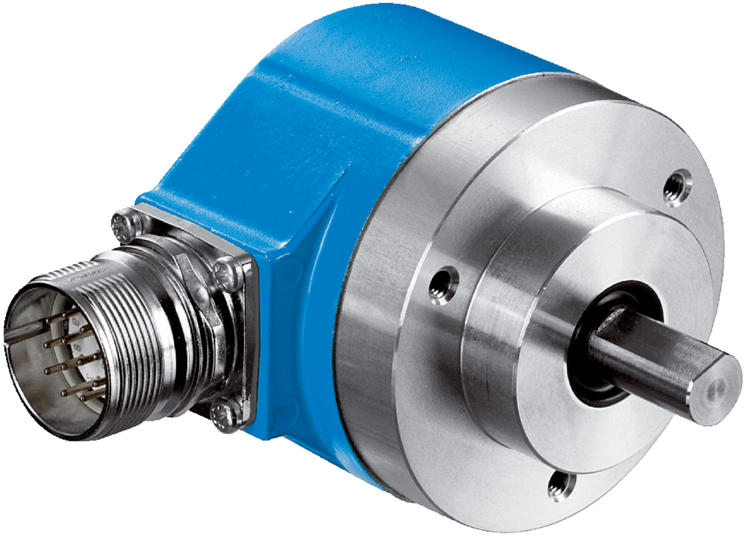
I. Typical Manifestations and Causes of MPOS vs. DPOS Errors
When the system detects persistent deviation between MPOS (Mechanical Position) and DPOS (encoder-feedback Electronic Position), the following phenomena typically occur:
1. Position Tracking Error: During servo motor operation, the monitoring display shows asynchrony between actual position and commanded position.
2. Accumulative Error: The deviation gradually increases over operating time, particularly noticeable during long-distance reciprocating movements.
3. Zero Drift: A fixed offset occurs during repeat positioning after the device returns to zero.
Based on user cases and technical documentation, the root causes of errors can be categorized as follows:
● Mechanical Transmission Issues: Loss of mechanical position due to loose couplings, belt slippage, excessive gear backlash, etc.
● Encoder installation defects: Signal jitter caused by shaft system concentricity deviation or loose encoder mounting bolts.
● Electrical interference: Signal noise resulting from parallel routing of power lines and encoder cables.
● Parameter configuration errors: Improper electronic gear ratio settings or mismatched filter parameters.
● Encoder hardware failures: Contaminated grating, magnetic pole decay in magnetic encoders, or signal processing chip malfunctions.
II. Systematic Troubleshooting Process
1. Mechanical Inspection
● Coupling and Drive Chain Inspection: Measure radial/axial runout between motor and load sides using dial indicators (must be <0.05mm).
● Backlash test: Record the difference in free play during forward and reverse rotation using a dial indicator. If exceeding the allowable value (e.g., 5μm), adjust the preload or replace the bearings.
● Encoder Installation Verification: Ensure flange surfaces are flush with no gaps. Verify shaft end screw torque meets specifications (e.g., CRT-recommended 0.5–0.8 N·m).
2. Electrical Signal Diagnostics
● Oscilloscope Inspection: Observe whether encoder A/B/Z signal waveforms are complete. Rule out glitches or amplitude attenuation (normal TTL signals should be 5V ±10%).
● Noise interference test: Temporarily use shielded twisted pair cable for dedicated routing and compare whether errors improve.
● Power supply stability: Check voltage fluctuations in the encoder power supply (e.g., 5V ±5%). Add a voltage regulator module if necessary.
3. Parameter and Software Verification
● Electronic Gear Ratio Verification: Recalculate numerator and denominator values based on mechanical reduction ratio. For example, with a 10:1 gearbox and 2500 ppr encoder resolution, the electronic gear ratio should be (pulses per motor revolution) / (pulses per load revolution) = 2500 × 4 / (10 × 2500 × 4) = 1:10.
● Filter Adjustment: Reducing the speed filter bandwidth in the servo drive (e.g., from 100Hz to 50Hz) suppresses miscounts caused by high-frequency noise.
● Zero Position Compensation: Manually input offset calibration via servo debugging software. Some systems support automatic compensation (e.g., Yaskawa Σ-7 drive's "MPOS-DPOS Auto Alignment" function).
III. Typical Solution Cases
Case 1: Periodic Error in Textile Machinery
Symptom: An eddy current spinning machine exhibited DPOS lagging behind MPOS by approximately 0.2mm during acceleration.
Troubleshooting: Spectral analysis revealed the error frequency was proportional to spindle speed. Ultimately, periodic slippage was traced to keyway wear in the encoder coupling.
Solution: Replaced the flexible coupling with a tapered sleeve keyless connection, reducing error to ±0.02mm.
Case 2: Cumulative Deviation in Laser Cutting Machine
Symptom: Y-axis deviation increased by 0.1mm per meter during straight-line cutting.
Cause: Encoder cable shared a conduit with servo power lines, causing pulse loss due to high-frequency interference.
Action: Rewired cables and installed magnetic rings. Simultaneously enabled the driver's "Pulse Loss Compensation" function, eliminating the deviation.
IV. Advanced Optimization Measures
1. Dual Encoder Redundancy Design: Implement motor-end encoders + direct load-end measurement (e.g., linear scales) in high-end equipment. Eliminate transmission chain errors through full closed-loop control.
2. Temperature Compensation: For magnetic encoders, enable temperature compensation algorithms when ambient temperature variations exceed ±10°C.
3. Routine Maintenance: Clean optical encoder grating discs every 6 months and inspect magnetic encoder pole spacing.
V. Differences in Manufacturer Technical Support
Different encoder brands exhibit varying tolerance levels for errors:
● Tamagawa Absolute Encoders: Pay attention to Endat protocol version compatibility; older drivers may misinterpret signals.
● Siemens Incremental Encoders: Use the SMC30 module for signal shaping.
● Domestic Encoders: Some products require manual calibration of the zero potentiometer.
Conclusion
Resolving MPOS-DPOS errors requires multidimensional analysis integrating mechanical, electrical, and software aspects. Practice indicates that 80% of failures stem from installation and wiring issues. We recommend establishing a standardized debugging process: mechanical calibration → signal quality testing → parameter fine-tuning → dynamic verification. For complex scenarios, employing high-precision laser interferometers for positional trajectory analysis can fundamentally enhance system stability.