


NPN and PNP transistors are two commonly used types in circuitry. They play a vital role in industrial automation and control systems. This article will explain the differences between NPN and PNP transistors and describe how to wire them with a PLC.
I. Differences Between NPN and PNP Transistors
Structure
An NPN transistor consists of a layer of N-type semiconductor sandwiched between two layers of P-type semiconductor. A PNP transistor, conversely, comprises a layer of P-type semiconductor sandwiched between two layers of N-type semiconductor.
Operating Principle
When an NPN transistor receives a positive voltage signal at its base, it allows current to flow from the collector to the emitter. A PNP transistor, when receiving a negative voltage signal at the base, will output current from the emitter to the collector.
Circuit Symbols
In the circuit symbol for an NPN transistor, the arrow points toward the transistor's base. In the circuit symbol for a PNP transistor, the arrow points toward the transistor's emitter.
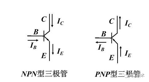
II. How to Wire NPN and PNP Transistors to a PLC
A PLC is an electronic device used to control automated equipment. It accepts digital input signals and performs logical operations based on pre-set programs to output control signals. NPN and PNP transistors can be connected to a PLC for digital input and output functions.
NPN Transistor Wiring
NPN transistors are commonly used as digital switches, serving as PLC inputs to control equipment activation. The wiring configuration for connecting an NPN transistor to a PLC is illustrated below:
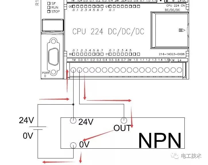 NPN Wiring Diagram
In the diagram above, the power supply is 24V DC. The collector of the NPN transistor is connected to the positive terminal of the power supply, and the emitter is connected to the input terminal of the PLC. When the base of the NPN transistor receives a positive voltage, it allows current to flow from the collector to the emitter. At this point, the PLC input detects a high-level signal. When the base of the NPN transistor does not receive a positive voltage, the PLC input detects a low-level signal.
Wiring of PNP Transistors
PNP transistors can also function as digital switches, serving as inputs to PLCs to control equipment activation. The wiring connection between PNP transistors and PLCs is shown in the diagram below:
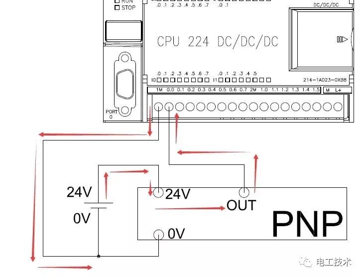 PNP Wiring Diagram
In the diagram above, the power supply is 24V DC. The emitter of the PNP transistor is connected to the positive terminal of the power supply, while the collector is connected to the input terminal of the PLC. When the base of the PNP transistor receives a negative voltage, it allows current to flow from the emitter to the collector. At this point, the PLC input detects a low-level signal. When the base of the PNP transistor does not receive a negative voltage, the PLC input detects a high-level signal.
Output Terminal Wiring
In addition to serving as input terminals, NPN and PNP transistors can also function as digital outputs. Connect them to the PLC's output terminals to control equipment power switches. The wiring method for NPN and PNP transistors is identical to that for the PLC's digital output terminals.
NPN and PNP Wiring Diagram
The PLC output terminal and the negative terminal of the power supply are connected to the emitter of the NPN or PNP transistor. The collector of the transistor is connected to the negative terminal of the device, while the positive terminal of the device is connected to the positive terminal of the power supply. When the PLC output terminal outputs a high-level signal, the transistor's base receives a positive voltage signal, allowing current to flow from the emitter to the collector, thereby energizing the device. When the PLC output terminal outputs a low-level signal, the transistor's base receives no voltage signal, causing the device to de-energize.
III. Summary
NPN and PNP transistors play crucial roles in industrial automation and control systems. They can function as digital input and output terminals to control the switching of automated equipment. The wiring configuration for NPN and PNP transistors depends on their application. When selecting transistors and PLC wiring, choices should be made based on specific operational requirements.