





Servo systems and variable frequency drives (VFDs) serve as core drive equipment in industrial automation, playing pivotal roles in motion control. While both involve motor speed regulation, they exhibit significant differences in design philosophy, technical architecture, and application scenarios. The following provides an in-depth analysis across dimensions including working principles, performance characteristics, and application contexts.
I. Core Principles and Technical Architecture Differences
1. Fundamentally Different Control Objects
Servo systems employ closed-loop control, utilizing encoders to provide real-time feedback on motor speed, position, and other parameters, enabling high-precision closed-loop regulation. Their core components include a servo motor (typically a permanent magnet synchronous motor), a high-resolution encoder (17 bits or higher), and a dedicated servo drive, achieving millisecond-level response times. For instance, the Yaskawa Σ-7 series servo system achieves position control accuracy of ±1 pulse.
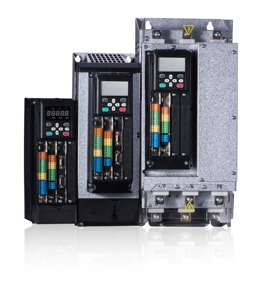
Inverters, primarily designed for AC induction motors, employ open-loop or simplified closed-loop (V/F control) methods. They adjust motor speed by modulating output frequency. Typical inverters like Mitsubishi's FR-A800 series focus on linear voltage/frequency matching rather than precise position tracking.
2. Algorithm Complexity Comparison
Servo drives incorporate triple-loop control (current loop, speed loop, position loop) utilizing advanced algorithms like fuzzy PID and feedforward compensation. For instance, Delta's ASDA-A3 series features resonance suppression, automatically identifying mechanical resonance points and adjusting gain parameters.
Inverter control algorithms are relatively simpler, predominantly employing Space Vector Modulation (SVC) or Direct Torque Control (DTC). While the ABB ACS880 series supports torque control, its dynamic response remains inferior to servo systems.
II. Analysis of Key Dynamic Performance Indicators
1. Response Speed and Bandwidth
The speed response bandwidth of servo systems typically exceeds 500Hz. For instance, the Panasonic MINAS A6 series achieves acceleration up to 3000 rad/s², making it suitable for applications requiring rapid start-stop cycles. Testing on a semiconductor packaging device demonstrated that the servo system can accelerate from 0 to 3000 rpm and achieve precise positioning within 0.2 seconds.
Inverters, constrained by motor characteristics, typically offer bandwidths of 50-100Hz for standard models. In a fan load test, an inverter required 3-5 seconds to accelerate to rated speed, exhibiting noticeable slip.
2. Low-Speed Performance Comparison
Servo motors maintain rated torque output even at 1rpm, with speed fluctuation rates below 0.01%. A machine tool feed axis test demonstrated that the servo system maintains positional accuracy within ±2 arcseconds at 5 rpm.
When driving asynchronous motors below 10% of rated speed, VFDs experience a 30%-50% torque drop and are prone to crawling. A conveyor belt application case required additional gear reducers for operation below 5 Hz.
III. Differentiation in Typical Application Scenarios
1. Main Battlefield of Servo Systems
● Precision Positioning: Semiconductor lithography machine workbench positioning accuracy reaches ±0.1μm.
● Rapid Response: Industrial robot joint axes require torque response at the 0.1ms level.
● Synchronous Control: Synchronization error of electronic gears in printing machinery <0.01°.
2. Dominant Applications for Variable Frequency Drives
● Energy-Efficient Speed Control: A cement plant achieved 35% electricity savings after retrofitting fans with VFDs.
● High-Power Drive Applications: Mining crushers utilize 2000kW-class high-voltage VFDs.
● Simple Speed Regulation: Constant torque loads like conveyor belts and mixers.
IV. Technological Convergence and Blurring Boundaries
Recent years have witnessed cross-technology phenomena:
1. Servo Capabilities in High-End VFDs
For instance, Siemens' G120X series supports encoder feedback with positioning accuracy reaching ±0.5°, approaching basic servo performance. In a packaging machinery case study, this model replaced a servo system, reducing costs by 30%.
2. Intelligent Evolution of Servo Systems
Next-generation servos integrate AI capabilities. For instance, Omron's 1S series features self-tuning algorithms that automatically detect load inertia. Testing shows an 80% reduction in commissioning time.
V. Selection Decision Tree and Cost Analysis
1. Key Selection Criteria
● Is position control required? Yes → Select servo.
● Is power > 50kW? Yes → Prioritize VFD.
● Is budget constrained? Yes → VFD solution reduces costs by 40-60%.
2. Total Lifecycle Cost Comparison
Analysis of an automotive production line reveals:
● Servo systems have higher initial investment but lower maintenance costs (15% savings over 5 years).
●Frequency converter solutions require frequent spare part replacements, resulting in higher total costs than servo systems.
VI. Emerging Technology Trends
1. Servo systems are moving toward integration, such as Mitsubishi's integrated drive/motor design reducing size by 50%.
2. Frequency converters focus on energy efficiency improvements, such as Invt's GD300 series using SiC devices to reduce losses by 20%.
3. Universal smart drives are emerging, like Bosch Rexroth's IndraDrive Mi, which switches between servo and VFD modes.
In summary, the fundamental difference between servo and VFD systems lies in varying requirements for control precision and dynamic response. As Industry 4.0 advances, both will deepen their strengths in respective domains while intensifying mid-market competition. Future "crossover" products may emerge, but core application boundaries will persist long-term.