


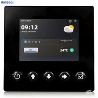


PLC stands for Programmable Logic Controller. It is a digital computer used in automation control systems, typically applied in industrial automation, robotics control, process control, and other fields. PLCs offer high programmability and flexibility, enabling the creation of distinct programs to fulfill varying application requirements and implement diverse control logic. Additionally, PLCs feature high stability, reliability, and ease of maintenance, making them widely adopted in industrial automation.
The primary function of a PLC (Programmable Logic Controller) is to receive, process, and output control signals, enabling the control and automated management of industrial equipment. The working principle of a PLC is as follows:
1. Input Signal Detection: The PLC receives input signals from various sensors and controllers, such as switch signals, temperature signals, pressure signals, etc.
2. Signal Processing: The PLC processes and calculates input signals through its internal processor and logic unit to determine whether to trigger corresponding control actions.
3. Control Signal Output: Based on the processing results, the PLC outputs corresponding control signals. These signals connect to actuators (such as motors, solenoid valves, etc.) via output modules to control the equipment.
4. Monitoring and Feedback: The PLC also monitors and provides feedback on output signals. It can monitor the status of output signals in real time and feed back the actual control results to the internal processor for correction and optimization.
In summary, the PLC operates by receiving, processing, and outputting control signals to achieve intelligent control and management of industrial automation equipment.
A programmable logic controller is essentially a computer dedicated to industrial control. Its hardware structure is fundamentally similar to that of a microcomputer. The basic components are shown in Figure 1, with detailed descriptions as follows:
1. Central Processing Unit (CPU): Responsible for scanning, processing, and outputting input signals, controlling and managing the entire system's operation.
2. Input Module: Converts signals from external sensors and actuators into digital signals for input to the CPU for processing and control.
3. Output Module: Converts digital signals output by the CPU into signals for connected actuators to achieve control objectives.
4. Memory: Stores programs, data, and system parameters for rapid access during operation.
5. Communication Interface: Facilitates communication with external devices such as human-machine interfaces, other PLCs, or computers.
6. Power Module: Supplies the required DC power to ensure the system operates normally.