RS485 is an industrial control scenario, the application of a very wide range of communication protocols, RS485 differential physical signals in the electromagnetic environment of the complex industrial site, there is a strong anti-jamming ability.
For engineers who usually focus on application software development, the use of RS485 for data transmission, as long as the focus on the serial port data transceiver can be, but in fact, at the hardware level, RS485 communication data send and receive, but also need to follow certain mechanisms.
RS485 communication interface characteristics
As a more commonly used communication method in the industrial field, the RS485 bus has many of the following characteristics:
1, transceiver output A, B between the level of +2V ~ +6V, is the logic of "1"; for -6V ~ -2V, is the logic of "0". Signal level than RS232 reduced, not easy to damage the interface chip. Another "enable" control signal, can make the transceiver in a high resistance state, cut off the connection with the transmission line.
2, the receiver's input sensitivity of 200mV, that is, when the level difference between the receiving end A, B 200mV can be output logic.
3, high transmission rate (10Mbps), transmission distance up to 1200m).
4, with multi-site transmission capability, that is, the bus allows hooking up to 128 transceivers, can establish a network of devices.
5, RS485 transceiver common-mode voltage range of -7V ~ +12V, only to meet the conditions, the entire network can work properly. When the network line common mode voltage beyond this range will affect the stability of communication, or even damage the interface.
RS485 transceiver control method
RS485 belongs to the half-duplex bus, in practice, the general use of host polling or token passing method to allocate the bus control, RS485 devices need to transmit and receive direction conversion.
The more common practice is that each RS485 device is normally in the receiving state, only in their own data to be sent to the sending state, the data is sent to switch back to the receiving state again.
The first: program commutation control
The most commonly used RS485 transceiver commutation method is the program commutation, that is, an I/O port by the MCU to control the RS485 transceiver device transceiver enable pin, in the usual way so that the RS485 transceiver device is in the receiving state.
The following chart, here 485 chip with TI's SN65LBC184, the maximum rate of 250Kbps, when there is data to be sent, the MCU will be RS485 transceiver device pin (network RS485_EN2) placed in the send state, after the completion of the data sent, and then the RS485 transceiver device to cut back to the receive state.
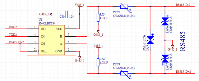
This way is simple and easy to do, no need to add extra costs, this method many people will know and basically all use the method.
The second type: automatic commutation
However, when we use a certain hardware platform industrial control motherboard or core board for secondary development, due to the industrial control motherboard or core board does not reserve enough I / O ports, so that the RS485 transceiver program commutation method can not be achieved.
In some specific cases, the underlying driver of the development platform is not open to the public, it is difficult to carry out secondary development of the underlying, in this case, even if there are enough I/O ports can not realize the program commutation.
For this reason, we need to use another commutation technology, that is, automatic commutation technology.
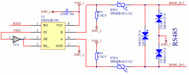
Auto commutation actually means that the enable pin does not need a separate I/O port to control, but is controlled by the transmit pin when it sends data.
To realize this method can be enabled there plus an inverter, the following chart, in the idle state, the serial port send signal TXD2 for the high level, after the inverter output low level, so that the SN65LBC184 is in the receiving state, and the RS485 bus due to the role of the pull-down resistor is in the state of A high and B low.
When sending data, the low level bit on the TXD2 signal line controls the SN65LBC184 to enter the transmit state and send the bit out. And the high level bit puts the SN65LBC184 in the receive state, which is indicated by the RS485 bus pull-up and down resistors placing the bus in the A high B low state, i.e., a high level is sent.
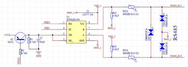
The inverter can also be replaced by a triode, as shown in the figure below, and the working principle is the same as adding an inverter.
However, this method has limited driving ability when sending high levels, so it will limit the communication distance, and is generally applicable to occasions where the distance is not far.