**1 **RS-485 Overview
Like RS-232, RS-485 is a serial communication standard. Its current official designation is TIA-485/EIA-485-A, but it is commonly referred to as the RS-485 standard. RS-485 is widely used in industries such as industrial automation, automotive, and building management. Within the EIA standards series, the RS-485 protocol is considered the most versatile, demonstrating excellent performance across all four serial communication standards.
The RS-485 bus overcomes the shortcomings of RS-232-namely, its short communication distance and low data rate. RS-485 supports data rates of up to 10 Mbit/s and has a theoretical communication distance of up to 1,200 meters. Unlike the single-ended transmission of RS-232, RS-485 uses differential transmission via a pair of twisted-pair wires, with one wire designated as A and the other as B.
**2 **RS-485 Physical Layer
The RS-485 physical layer is responsible for transmitting raw data between devices and the physical transmission medium. It handles the conversion of electrical signals to digital data, while also defining voltage levels, timing, data rates, and other parameters.
① Differential Signals
Long-distance cabling results in signal attenuation and increases the likelihood of noise and interference. This manifests as changes in voltage amplitude on cables A and B. However, the advantage of using differential lines is that subtracting the difference between the two signals cancels out the interference, allowing a normal signal to be output. The ability of a differential receiver to ignore identical voltages on both signal lines is called common-mode rejection.
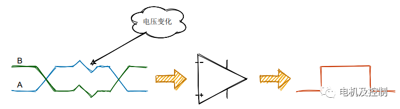

The standard specifies that logic 1 is +2V to +6V, and logic 0 is -6V to -2V.
RS-485 does not require a specific bus voltage; it only considers the minimum differential voltage. Over longer cable lengths, the voltage received by the receiver may drop to +/- 200 mV, which is still perfectly acceptable for RS-485-this is one of the advantages of RS-485.
Many transceivers meet or even exceed the TIA/EIA-485A standard; in practical applications, however, the device's specified parameters take precedence. For example, the minimum negative input threshold for a certain transceiver is -200 mV.

② Signal Definitions
RS-485 Signal Line Definitions
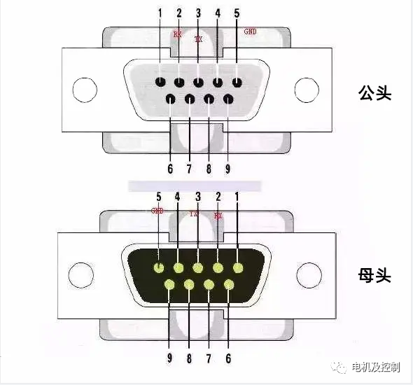
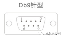
Schematic Diagram of DB9 Male and Female Connectors
| DB9 | Ring Indicator | Pin Name |
|
1 |
CD | Carrier Detect |
| 2 | RXD | Receive Data |
| 3 | TXD | Transmit Data |
| 4 | DTR | Data Terminal Ready |
| 5 | GND | System Ground |
| 6 | DSR | Data Ready |
| 7 | RTS | Transmit Request |
| 8 | CTS | Clear to Transmit |
| 9 | RI | Ring Indicator |
DB9 Pin Assignment
Carrier Detect (CD) This control signal is used when the modem notifies the computer that it has detected a carrier signal that the computer can use for data transmission.
Receive Data (RXD) This line is used for data transmission between two sources. An example is data received from the modem and transmitted to the computer.
Transmit Data (TXD) This is the line that actually carries the transmitted data.
Data Terminal Ready (DTR) This signal indicates that the computer is ready to transmit data.
System Ground (GND) Refers to a physical connection to ground, used as a baseline for measuring voltage in a circuit or as a common path for returning current.
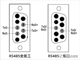
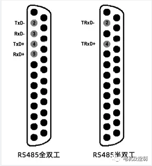
Pinout Diagram for 25-Pin RS-485 Half-Duplex and Full-Duplex Connectors
Compared to the DTR signal, the Data Set Ready (DSR) signal notifies a computer or terminal that the modem is operational and capable of receiving data.
For this signal, a positive voltage is required to enable the Ready to Send (RTS) signal. This indicates that interference-free transmission is possible between the data set and the data terminal.
After a connection is established between the data terminal and the modem, the Clear to Send (CTS) signal is transmitted to confirm that the data terminal has acknowledged that communication can begin.
The Ring Indicator (RI) serves to alert the modem operating the data set that a low-frequency signal has been detected. This signal merely warns the data terminal and does not affect data transmission between the devices.
Pin assignments connect to DB9 and DB25 connectors via 2 and 4 contacts, respectively.
The TxD+ and TxD- lines on the DB25 connector transmit data, while the RxD+ and RxD- lines carry received data. Because these are differential signals, they can be transmitted over longer distances.
The RS-485 interface outperforms the RS-232 protocol in terms of transmission distance and data rate. It supports data rates of 30–35 Mbps over distances of up to 10 meters. Data rates of 100 Kbps can be achieved over distances of up to 1,200 meters. RS-485 is primarily used in multipoint configurations that take advantage of its balanced differential interface.
As shown in the RS-485 cable pinout, this interface features all signals in a differential configuration.
● The CTS+ and CTS- signals, as well as the RTS+ and RTS- signals, are used as handshaking control signals.
● TxD+ and TxD- are used for data transmission.
● RxD+ and RxD- are the lines used to receive data.
A multipoint configuration can connect up to 32 devices to a single master control device. The VSAT NMS (Network Management System) is one such example. In this implementation, software running on a PC can monitor and control various subsystems. These include the MUX, modem, RF up/down converters, and other network components. For this type of implementation to function properly, correctly wired RS-485 connectors are required on both the PC running the NMS application and all connected subsystems.
RS485 Interface Description
The RS485 (EIA485) interface has proven to be extremely robust and, due to its multi-point topology, has become the most popular communication protocol in the industrial sector. The RS422 protocol is similar to RS485 in that both use differential signals for data transmission.
There are two types of RS-485:
● Half-duplex RS-485 has 2 pins.
● Full-duplex RS-485 has 4 pins.
You can use full-duplex mode when you need to send and receive data simultaneously. In half-duplex mode, you can only send or receive data at any given time.
The voltage range on the line is -7 V to +12 V.
There is no specific connector type required to implement the RS-485 protocol, but in most cases, DB9 connectors or terminal blocks are used.
Specific RS-485 connectors may have different pin configurations. You can determine the actual configuration based on the documentation provided with the device.
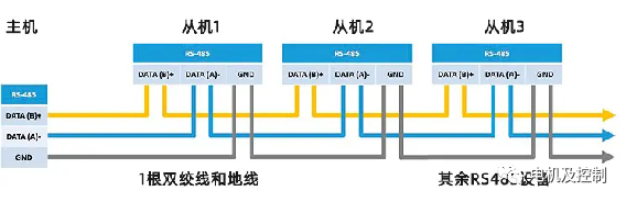 Connecting an RS-485 Device with 2 Pins-Half-Duplex RS-485 Pin Allocation
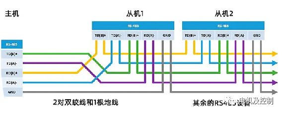 Connecting an RS-485 Device with 4 Pins-Full-Duplex RS-485 Pin Allocation
Many RS-485 converters today are compatible with RS-422, so you'll often see signals labeled T/R+ and T/R- on these converters, which correspond to RS-485's A+ and B-.
③ Topology
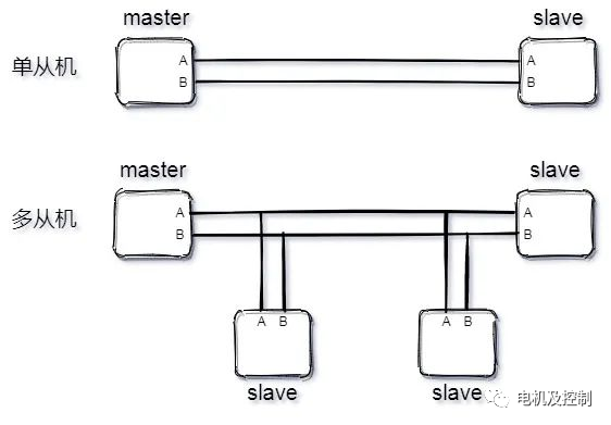
RS-485 supports both two-wire and four-wire configurations. The four-wire configuration is limited to point-to-point communication and is rarely used today; the two-wire configuration is more commonly used. This configuration employs a bus topology, allowing up to 32 nodes to be connected on a single bus.
Like I²C, the RS-485 bus operates in a master-slave mode. It supports both point-to-point single-slave mode and multi-slave mode, but does not support multi-master mode.