





Brushless DC (BLDC) motors are an integral part of the industrial manufacturing plant and are used in servo, actuation, positioning and variable speed applications. In these applications, precise motion control and stable operation are critical. Since BLDCs operate on the principle of a moving magnetic field to generate motor torque, the main control challenge when designing an industrial BLDC system is to accurately measure the torque and speed of the motor.
To capture the torque of a BLDC motor, two of the three induced phase currents need to be measured simultaneously using a multichannel synchronous sampling analog-to-digital converter (ADC). A microcontroller with the appropriate algorithms calculates the third instantaneous phase current. This process provides an accurate and instantaneous record of the motor condition, which is a critical step in the development of a robust and highly accurate motor torque control system.
This paper will briefly discuss the issues associated with achieving accurate torque control, including a cost-effective method of realizing the required shunt resistor. It will then introduce Analog Devices' AD8479 precision differential amplifier and AD7380 dual-channel sample-approximation successive-approximation-register ADC (SAR-ADC) and show how they can be used to obtain accurate phase measurements for reliable system design.
BLDC Motor Principle of Operation
BLDC motors are permanent magnet synchronous motors with a counter electromotive force (EMF) waveform. The observed terminal counter electromotive force is not constant; it varies with rotor torque and speed. Although a DC voltage source cannot directly drive a BLDC motor, the basic principle of operation of a BLDC is similar to that of a DC motor.
A BLDC motor consists of a rotor with permanent magnets and a stator with induction windings. This motor is essentially a flipped DC motor in which the brushes and commutator are eliminated and the windings are then connected directly to the control electronics. The control electronics take over the function of the commutator and energize the windings in the correct sequence to obtain the desired motion. The energized windings rotate around the stator in a synchronized, balanced pattern. The energized stator windings guide the rotor magnets and switch when the rotor is aligned with the stator.
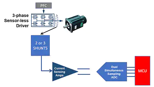
BLDC motor systems require a three-phase sensorless BLDC motor driver that generates current in the motor's three windings (Figure 1). The circuit is powered by a digital power factor correction (PFC) stage with inrush control to provide stable power to the three-phase sensorless driver.
Figure 1: The motor control system includes a PFC for stabilizing the power supply, a three-phase sensorless driver for the BLDC motor windings, shunt resistors and current-sense amplifiers, a synchronous amplifier ADC, and a microcontroller.
Three excitation currents drive the BLDC motor, each of which excites and generates a different phase in the winding, these phases totaling 360°. The different phase values are important: since the total excitation of the three branches is maintained at 360°, they are evenly offset to maintain 360°, e.g. 90° + 150° + 120°.
Although the currents in all three windings of the system must be known at any given time, to do this in a balanced system it is only necessary to measure the currents in two of the three windings and calculate the third winding using the microcontroller. These two windings can be detected simultaneously using a shunt resistor and a current detection amplifier.
A two-channel synchronous sampling ADC is required at the end of the signal path to send the digital measurements to the microcontroller. The amplitude, phase and timing of each excitation current provides the motor torque and speed information needed for precise control.
Current Sensing with PC Board Copper Resistors
While there is much to be concerned about in this precise measurement and data acquisition design, the process begins at the front end with the need to develop an effective, low-cost way to sense the phase signal of the BLDC motor windings. This can be accomplished by placing a small value inline PC board resistor (RSHUNT) and using a current-sense amplifier to detect the voltage drop across this small resistor (Figure 2). Assuming the resistor value is low enough, the voltage drop is also low and the measurement strategy has minimal effect on the motor circuitry.
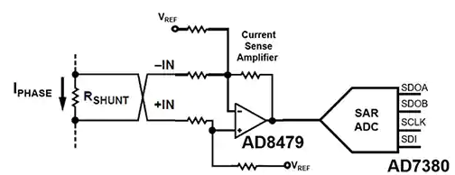
Figure 2: A motor phase sensing system uses a current shunt resistor (RSHUNT) with a high-precision amplifier (e.g., Analog Devices' AD8479) and a high-resolution ADC (AD7380) to measure instantaneous motor phase.
In Figure 2, the current-sense amplifier captures the instantaneous IPHASE x RSHUNT voltage drop. The SAR-ADC then digitizes this signal. The shunt resistor selection value involves the interaction between RSHUNT, VSHUNT, ISHUNT and the amplifier input error.
An increase in RSHUNT will result in an increase in VSHUNT. The good news is that this will mitigate the significance of the amplifier's voltage offset (VOS) error and input offset current (IOS) error. However, the ISHUNT x RSHUNT power loss of a larger RSHUNT reduces the power efficiency of the system. Similarly, the RSHUNT power rating can affect system reliability because ISHUNT x RSHUNT power dissipation creates a self-heating state, which can cause the nominal RSHUNT resistance to change.
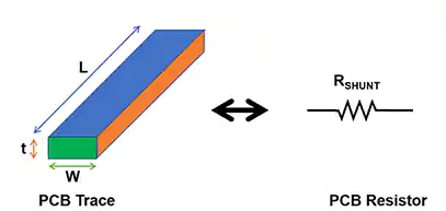
For RSHUNT, special-purpose resistors can be obtained from several suppliers. However, there is a low-cost alternative to manufacturing PC board printed wire resistors for RSHUNT using careful layout techniques (Figure 3).
Figure 3: Meticulous PC board layout techniques provide a cost-effective way to create appropriate RSHUNT values.
Calculating PC Board Printed Wire Resistance for RSHUNT
Because of the extreme temperatures that can occur in industrial applications, it is important to consider temperature factors in the design of circuit board shunt resistors. In Figure 3, the temperature coefficient (α20) of a copper PC board printed wire shunt resistor is approximately +0.39%/°C at 20°C (this coefficient varies with temperature). Length (L), thickness (t), width (W), and resistivity (rñ) determine PC board printed wire resistance.
If the PC board has 1 ounce (oz) of copper (Cu), the thickness (t) is equal to 1.37 inches per thousand, and the resistivity (r) is equal to 0.6787 microohms (µW) per inch. the PC board printed wire area is measured in printed wire boxes ( ), or L/W area. For example, a 2-inch (in.) print line with a width of 0.25 inches corresponds to 8 structures.
Using the above variables, calculate the printed wire resistance R for 1 ounce of copper on a PC board at room temperature by (Equation 1):

Formula1
where T = temperature of the resistor.
For example, starting with a maximum current of 1 ampere (A) per BLDC motor branch on a 1 ounce copper PC board, an RSENSE length (L) of 1 inch, and a printed wire width of 50 mils (0.05 inches), equations 2 and 3 can be used to calculate RSHUNT at 20°C:

Formula 2

Formula 3
Calculate the power dissipation of this resistor at a shunt current of 1 A using Equation 4:

Formula 4
Synchronous Sampling ADC Conversion
The ADC in Figure 2 converts the voltage at a point in the phase cycle to a digital representation. The key point is that this measurement should include the synchronized phase voltages of all three windings. This is a balanced system, so as mentioned earlier, only two of the three windings need to be measured; an external microcontroller will calculate the phase voltage of the third winding.
The ADC for this motor control system is the AD7380 dual-channel synchronous sampling SAR-ADC (Figure 4).
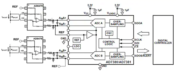 Figure 4: A fast, low-noise, dual-channel synchronous sampling SAR-ADC (e.g., AD7380) captures the instantaneous state of two motor windings.
In Figure 4, the AD8479 is a precision differential amplifier with a very large input common-mode voltage range (±600 volts) to withstand wide motor current drive offsets from three-phase, sensorless drives.The AD8479's characteristics allow it to replace expensive isolation amplifiers in applications where current isolation is not required.
Key features of the AD8479 also include low compensation voltage, low compensation voltage drift, low gain drift, low common-mode rejection drift, and excellent common-mode rejection ratio (CMRR) to accommodate fast motor variations.The AD7380/AD7381 are 16-bit/14-bit, high-speed, low-power, dual-channel, synchronous-sampling SAR-ADCs, respectively, with throughput rates up to 4 M samples per second. The differential analog inputs accept a wide range of common-mode input voltages and have a built-in 2.5-volt buffered reference (REF) voltage source.
For precise torque and speed control, the dual-channel synchronous sampling SAR-ADC architecture captures the output of the current-sense amplifier on-the-fly. For this purpose, the AD7380/AD7381 incorporate two identical ADCs with synchronous clocks, and each has a capacitive input stage with a capacitive charge redistribution network (Figure 5).
Figure 5: Shows the ADC conversion stage for one of the two channels of the AD7380. Signal acquisition starts when SW3 is open and SW1 and SW2 are closed. At this point, the voltage across CS varies with AINx+ and AINx-, causing the comparator inputs to become unbalanced.
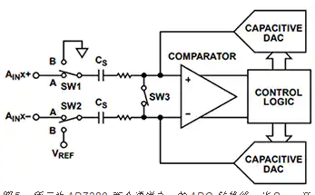
In Figure 5, VREF and ground are the initial voltages across the sample capacitor CS. If SW3 is opened and SW1 and SW2 are closed, signal acquisition is initiated. When SW1 and SW2 are closed, the voltage across the sample capacitor CS varies with the voltage at AINx+ and AINx-, causing the comparator inputs to lose balance. SW1 and SW2 are then opened and the voltage across CS is captured.
The CS voltage capture process involves a digital-to-analog converter (DAC), which adds and subtracts a fixed amount of charge from CS to bring the comparator back into balance. At this point, the conversion is complete, opening SW1 and SW2 and closing SW3 to remove the residual charge and prepare for the next sampling cycle.
During the DAC conversion, the control logic generates the ADC output code and accesses the device data through the serial interface.
Summary
To accurately measure BLDC motor torque and speed, accurate, low-cost shunt resistors are required first. As mentioned above, this resistor can be cost-effectively implemented using PC board printed wires.
By adding this device to the combination of the AD8479 current-sense amplifier and the AD7380 synchronous-sampling SAR-ADC, designers can create a robust, high-precision torque and speed control system measurement front-end for motor control applications in harsh environments.