





Designers of industrial automation systems face an increasing number of challenges. Mounting such equipment in racks leads to increased size and thermal constraints. In harsh industrial environments, sensitive electronic equipment requires strictly regulated voltages, and customers demand higher performance and functionality. In Part 1 of this two-part series, we will explore the conflicting demands on industrial power supplies and the trade-offs associated with common solutions.
Introduction
Industrial automation system design presents unique challenges. In fact, it is a story of conflicting demands. The introduction of low-cost modular racks to house system components such as programmable logic controllers (PLCs) and I/O modules has imposed severe space and thermal constraints on engineers and solutions. These challenges are further complicated by the need to ensure highly reliable operation in harsh environments susceptible to dirt, humidity, and vibration.
Additionally, customers expect enhanced functionality in subsequent generations of automation systems, all without increasing power consumption, device size, heat generation, or cost. Such enhanced functionality is often based on advancements in electronic technology, but it often comes at a cost: stricter power tolerances and surges in voltage levels that must remain stable despite imperfect power sources.
However, engineers do not want to spend valuable project time designing a power supply that goes unnoticed by customers and is often considered a waste of valuable space. Instead, engineers prefer to focus on features that clearly distinguish their automation systems from competitors.
Semiconductor suppliers have responded to the conflicting demands of industrial automation system designers by introducing modules that integrate many key power supply functions into a single device. However, modules designed to be powered by 12, 24, or 48VDC power supplies used in industrial automation systems must be protected by voltage clamps or use asynchronous switching technology to withstand voltage spikes that plague the main power supply. Both solutions result in larger, more expensive, and less efficient power systems-exactly what system engineers are trying to avoid.
This application note is Part 1 of our two-part series on industrial control regulators. Here, we discuss industrial control architectures and their unique power supply architectures, which present design challenges. In Part 2 of this series, we will discuss the next generation of power devices that leverage the latest silicon manufacturing technologies combined with innovative chip designs.
Industrial Control Architectures
While 24VDC has become the de facto voltage for most industrial control applications (especially those using PLCs), 12VDC is also common, typically as a battery backup voltage or supplied by alternative energy sources such as photovoltaic (PV) panels. The recent introduction of Power over Ethernet (PoE) has also encouraged industrial automation manufacturers to design devices powered by the 48VDC power supply specified by that standard. A typical industrial control system using a 24VDC power supply is shown in Figure 1.
 Figure 1. Typical industrial control system.
The system includes I/O modules for receiving information from sensors or sending commands to actuators, multi-channel digital inputs, multi-channel analog inputs and outputs, communication functions, and a processor (CPU) linked via a digital bus. PLCs typically provide computing power. Power is supplied by mains power, stepped down to 24VDC, and distributed via a backplane.
Upon closer examination of the system's power supply, it becomes evident that the complexity increases due to the varying voltage and current levels required by different system components. Figure 2 illustrates a small portion of the power supply architecture. The 120VAC/230VAC main power supply is initially stepped down using industrial power modules to standard 12VDC or 24VDC system backplane power supplies. At the system level, this backplane voltage is further stepped down to the lower voltage levels required by individual components.
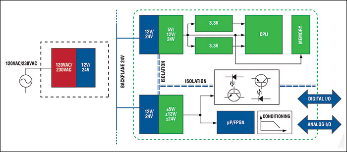 Figure 2. Part of the power supply architecture of an industrial automation system
For example, a PLC can consist of a microprocessor, a digital signal processor (DSP), and a field-programmable gate array (FPGA). These devices require a voltage range of 5V to 1V. However, the entire PLC may require up to 3.5A of current. Similarly, multi-channel analog I/O modules require ±15V and 5V power supplies for various amplifiers, analog-to-digital converters (ADCs), and multiplexers (MUXes) with currents up to 500mA.
To complicate matters further, designers must consider transient voltage spikes ("overvoltages"), which can affect power supply delivery through events such as lightning strikes on the power distribution network or through rapid switching of heavy loads sharing the same power circuit with industrial automation systems. Voltage spikes may also occur within the power supply architecture itself, such as when power supply modules step down the power supply voltage to 12VDC or 24VDC, particularly when using switch-mode type devices.
These overvoltage events are so common that organizations such as the International Electrotechnical Commission (IEC) recommend that engineers design their systems to withstand them. For example, IEC 60664 addresses insulation coordination in low-voltage (1kVAC and 1.5kVDC) systems, stating that "Class II" equipment (including types used in industrial automation) powered by 24VDC derived from the mains should be designed to withstand overvoltages up to 60V.
DC-DC Voltage Regulation Basics
DC-DC voltage conversion (or "regulation") is big business, and semiconductor suppliers have invested heavily in developing a wide range of products for all applications. Devices are divided into two groups: low-dropout regulators (LDOs), also known as linear regulators; and switching regulators.
When carefully matched to the application's operating characteristics, switching regulators typically offer higher efficiency over a wide input voltage range compared to LDOs. Additionally, switching regulators can easily boost ("step-up"), buck ("step-down"), and invert voltages. (Note that certain parts of industrial automation system power supplies require inverted voltages. In contrast, LDOs can only buck.)
Compared to the simple and user-friendly LDO, switching regulators have one drawback: their design is more complex. This is because output filtering is required to attenuate voltage and current ripple generated by high-frequency switching operations. This can cause issues for sensitive chips and generate electromagnetic interference (EMI). Despite this, engineers designing many contemporary applications are increasingly favoring switching regulators.
The key to how switching regulators work is the use of metal-oxide-semiconductor field-effect transistors (MOSFETs) as switching devices. When the MOSFET is on, current flows to both the load and an external inductor that stores energy. When the MOSFET is off, the inductor provides the stored energy to the load.
Pulse width modulation (PWM) is typically used to control the output voltage. The frequency remains constant, while the pulse width (the "on-time") is adjusted to provide the desired voltage. The high-frequency switching of the regulator minimizes losses in the system while maintaining a relatively stable voltage output across a range of input and load conditions.
In an asynchronous topology switching regulator (Figure 3), the energy stored in the inductor and then transferred to the load during the MOSFET off cycle does not flow directly to the load. Instead, it is propagated through an external Schottky diode. If the inductor is selected according to the expected load, the switching regulator will operate in continuous conduction mode, providing stable regulation.
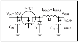 Figure 3. Asynchronous buck regulator circuit.
The ultimate efficiency of this type of switching regulator is primarily determined by two factors: the forward voltage drop of the external Schottky diode and the reverse leakage current characteristics of the device. In modern devices, the forward voltage drop is approaching the limit of approximately 0.3V. This may not seem like much, but it does result in continuous power consumption and reduced efficiency.
Replacing Schottky diodes with MOSFETs improves efficiency because the on-resistance (Ron) of transistors can be reduced using advanced manufacturing techniques, resulting in lower forward voltage (and losses) than the original diodes. The two MOSFETs in this circuit must operate synchronously, with one conducting and the other blocking. (See Figure 4.)
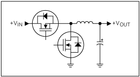 Figure 4. Synchronous buck regulator circuit.
The second MOSFET of the so-called synchronous regulator can be integrated into the module. In addition to eliminating the need for an external Schottky diode, this simplifies circuit design and reduces the bill of materials (BOM).
A side effect of synchronous regulator design is that current flows bidirectionally in the inductor due to the switching operation of the two MOSFETs (i.e., doubled inductor losses). This contrasts with the unidirectional flow in asynchronous types. In synchronous regulators, losses are typically small, but at lower loads, device efficiency may be lower than that of equivalent asynchronous types, resulting in greater losses.
Major semiconductor suppliers have addressed this drawback using various technologies. For example, Maxim Integrated has introduced a series of high-voltage synchronous regulators, such as the MAX17503, featuring a MODE function that allows the device to operate in three selectable modes: PWM, pulse frequency modulation (PFM), and discontinuous conduction mode (DCM). PWM is used for normal operation. PFM improves efficiency at lower loads by eliminating reverse inductance current and skipping pulses. DCM also eliminates reverse inductance current to improve efficiency at lower loads but does not skip pulses. This makes DCM suitable for frequency-sensitive applications.
Summary
High-voltage, high-output current synchronous regulators meet the demand for compact, efficient, and easy-to-design power modules in industrial automation. Several factors have contributed to the industrial power supply challenge, but a high-voltage synchronous regulator architecture is now available to address all requirements. Although the current selection of suitable components is limited, the range continues to expand to meet all DC-DC voltage conversion requirements for typical systems, with power outputs ranging from hundreds of milliamps to several amperes. In Part 2, we will discuss how new innovations in synchronous regulators can help address power consumption challenges