What is IO-Link
IO-Link is a digital communication protocol for industrial automation, originally proposed by Siemens and now an international standard. It aims to enable connectivity and communication between industrial equipment and control systems. It facilitates bidirectional communication between sensors, actuators, and other industrial devices with controllers (such as PLCs), enabling real-time transmission of data and control signals.
IO-Link is a serial communication protocol (similar to the I2C bus) that serves as a communication standard between industrial automation controllers and industrial actuators or sensors. It represents the "last few feet" technology standard for bridging communication networks to the field.
Why is IO-Link needed?
IO-Link technology is essential due to the following technical advantages:
Real-time data transmission and control: In industrial automation, real-time data transfer is critical for precise equipment control and monitoring. IO-Link provides a high-speed, reliable digital communication channel, enabling sensors and actuators to rapidly transmit data to control systems for real-time control and monitoring.
IO-Link enables bidirectional communication: It not only receives commands and configuration data from the control system but also transmits parameters and status information back to the control system. This intelligence allows devices to adapt to varying production demands and operating conditions, enhancing production line flexibility;
Simplified Installation and Maintenance: IO-Link devices can be parameterized and configured via digital communication, reducing manual setup errors and streamlining installation and maintenance processes. Additionally, IO-Link transmits diagnostic information, helping engineers quickly identify and resolve issues to minimize downtime.
Fault Diagnosis and Predictive Maintenance: Diagnostic data transmitted via IO-Link assists enterprises in fault diagnosis, enabling timely problem detection and resolution to reduce production interruptions and losses. Furthermore, by monitoring device status and performance data, predictive maintenance becomes achievable, enabling proactive prevention of equipment failures and further boosting production efficiency. Standardization and Interoperability: IO-Link is an internationally standardized communication protocol. Devices from different manufacturers adhere to the same communication standards, ensuring interoperability between diverse equipment. This allows businesses to flexibly select and integrate devices from various suppliers without compatibility concerns.
The Development of IO-Link
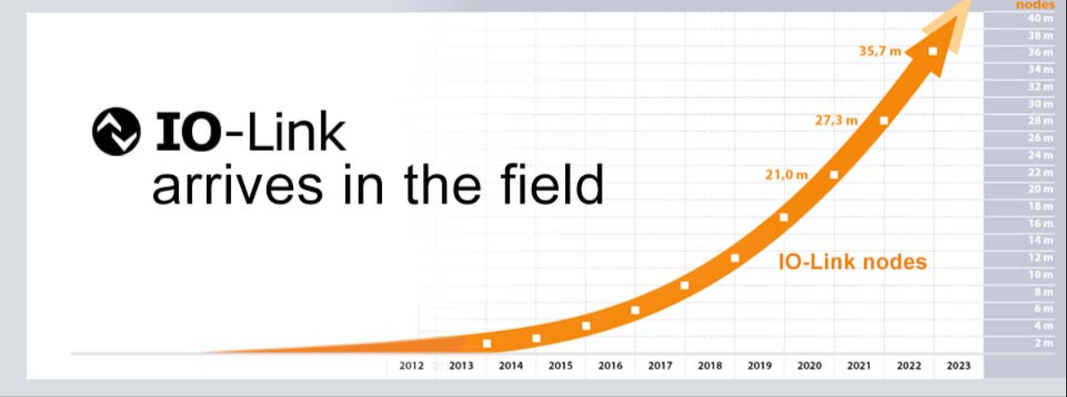
The number of I0-Link nodes has grown exponentially in recent years, reaching 6 million nodes as early as 2017.
Sensor Mode
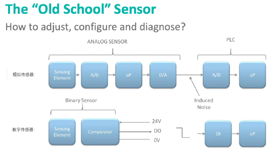
Traditional data acquisition sensors fall into two categories:
1. Analog sensors: Analog sensor values are converted into digital values via A/D conversion. The microprocessor (uP) reads these digital values, which are then converted back into analog signals via D/A conversion for transmission to the PLC. The PLC reconverts these analog signals into digital signals using its A/D converter. The PLC's microprocessor reads the digital values to obtain sensor information.
2. Binary digital sensors: Transmit binary digital level signals between the sensor and PLC via digital output (DO) and digital input (DI) ports.
Single-Port Binary Digital Sensor Driver
First, what is a sensor driver? What does it do?
A sensor driver is a software or hardware component that controls and operates sensor devices, enabling them to function properly and communicate with other systems. The role of a sensor driver is to convert the physical quantities generated by sensors into digital signals,
then transmit these signals to higher-level applications or systems for processing, analysis, and decision-making.
My understanding is that the sensor driver serves as an intermediary layer between the lowest-level sensors and upper-level applications. Without this intermediary, the digital or analog signals collected by sensors would simply propagate aimlessly through the circuitry. With the sensor driver in place, the data gathered by the underlying sensors gains a name, a direction, and various attributes. This enables upper-level applications to recognize the origin of the data, understand what physical quantities it represents, and issue corresponding action commands.
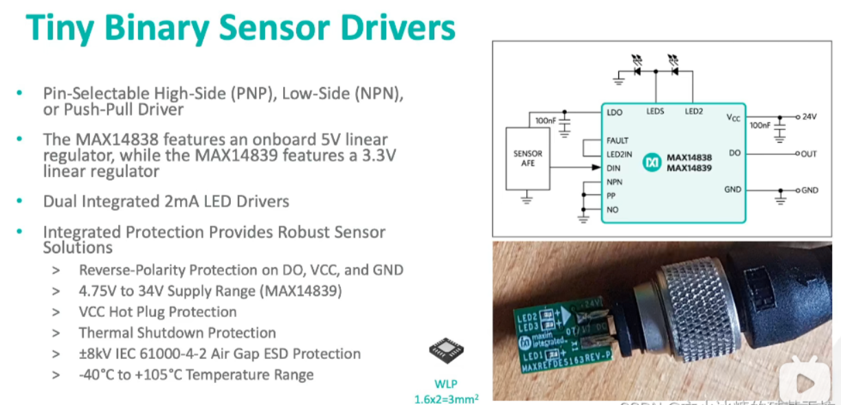
Functions of Binary Digital Sensors and Drivers:
Signal Adaptation: Binary digital sensors may generate specific digital signals representing different states or events, such as switch status or button presses. Sensor drivers adapt these signals into electrical signals readable and interpretable by other systems, such as voltage signals.
Signal Amplification or Attenuation: Sometimes sensor output signals require amplification or attenuation to meet subsequent circuit requirements. Sensor drivers can amplify or attenuate signals to ensure precise signal transmission;
Electrical Isolation: To isolate noise or interference between sensors and other circuits, sensor drivers provide electrical isolation, ensuring the accuracy and stability of sensor signals;
Signal filtering: Sensors may be affected by environmental noise. Sensor drivers can provide filtering functions to eliminate this noise and deliver more reliable signals;
Logic Conversion: Some digital sensors' output signals may require logic conversion, such as signal inversion or combining multiple signals. Sensor drivers can execute these logic conversion operations;
Sensor Power Supply: Certain digital sensors may require external power to function properly. Sensor drivers can provide the appropriate supply voltage for the sensor;
Interface Compatibility: Sensor drivers offer various interface options to connect sensors to different systems or devices, such as analog signals, digital signals, serial communication, etc.
Disadvantages of Single-Port Binary Digital Sensor Drivers:
1. Data transmission is unidirectional read-only. What if control operations are required?
2. Data has only two states: 0/1. How can more information be transmitted?
IO Device System
IO-Link sensors show no measurement deviation
Traditional analog signals (temperature, pressure, etc.) require conversion between analog and digital formats during transmission. This conversion process introduces data discrepancies that affect the accuracy of the final results.

When connected via IO-Link, measured values are transmitted digitally from the sensor directly to the controller, ensuring that the transmitted data values always correspond exactly to the measured values.
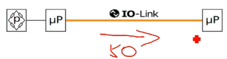 IO-Link connectivity also eliminates the susceptibility to surrounding electromagnetic interference inherent in traditional analog signal transmission.
Composition of the IO-Link Network
I0-Link can be used with various end devices:
Sensors: Temperature, pressure, photoelectric, flow... I0-Link sensors provide digitized sensor data and support remote configuration and monitoring.
Actuators: Solenoid valves, motor drivers, servo drives... These actuators enable remote control, monitoring, and diagnostics via I0-Link.
Analog-to-Digital Converters (ADC/DAC): By connecting digital-to-analog converters, analog signals can be output from the IO-Link network.
Identification Devices: Such as RFID readers/writers, barcode scanners, etc., to enable object identification and tracking functions.
IO-Link Interconnection Bus (Unified Wiring Standard)
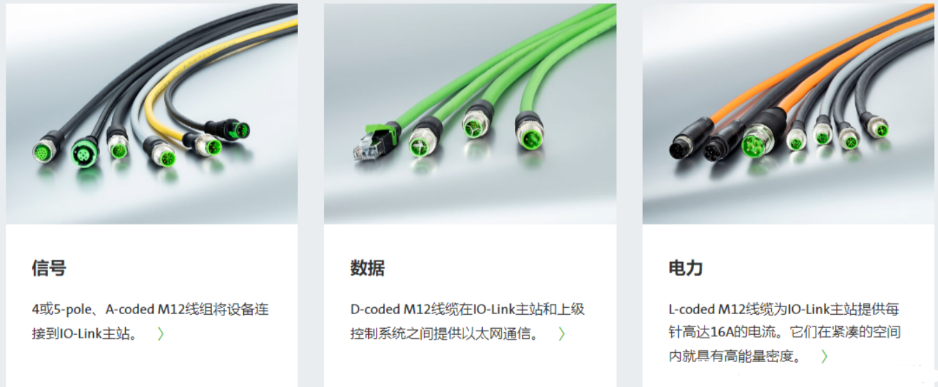
IO-Link connections utilize the following three distinct connector types:
1. Signal cable: Connects the master to the hub or IO-Link terminal device. The physical layer signals of IO-Link are transmitted over the signal cable (standard three-core cable).
2. Data cable: Connects the master to higher-level control devices, such as Ethernet equipment.
3. Power cable: Supplies high current to the master
IO-Link Unified Wiring Standard:
• The IO-Link Master requires only a standard 3-core cable to connect all IO-Link devices
• Both digital switch signals and analog signals can communicate data with the upper-level controller via this 3-core cable
• Prediction: In the future, all analog signals, RS232, and RS485 will be replaced by IO-Link
IO-Link Sensor Specification
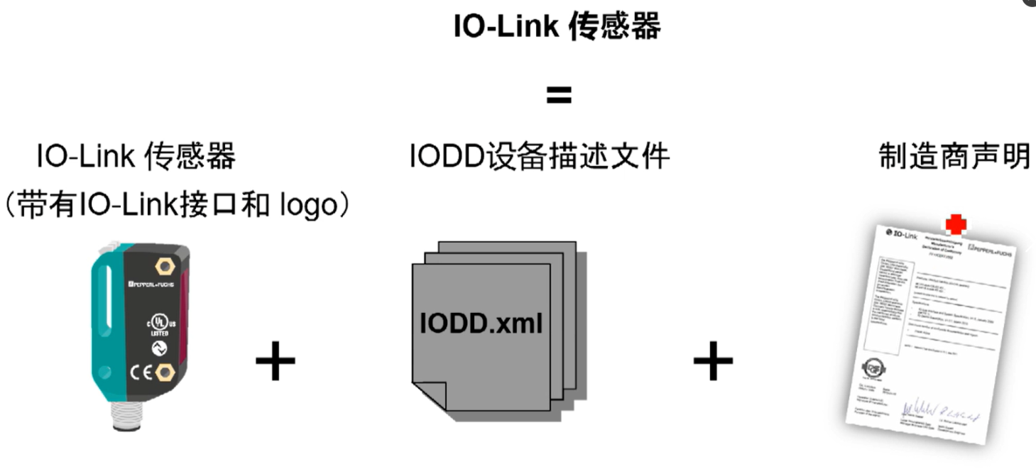
IO-Link Sensor = IO-Link sensor (with IO-Link interface and logo) + IODD device description file + manufacturer declaration
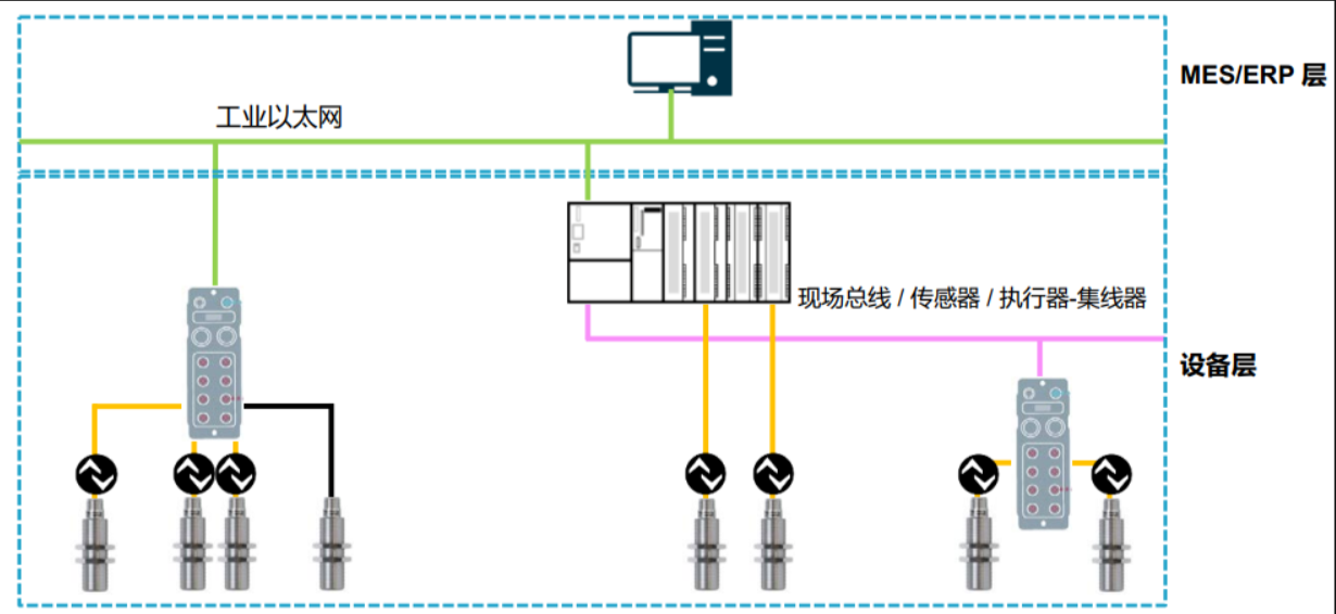
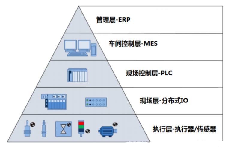
 The Position of IO-Link in Industrial Internet
The final 1 meter to the network
IO-Link Communication
Communication Interfaces and Data Types
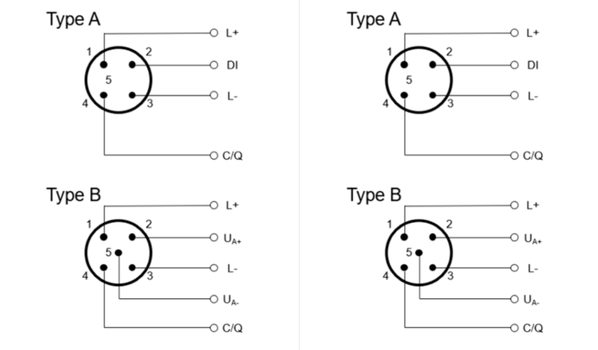
What is the difference between Type A and Type B?
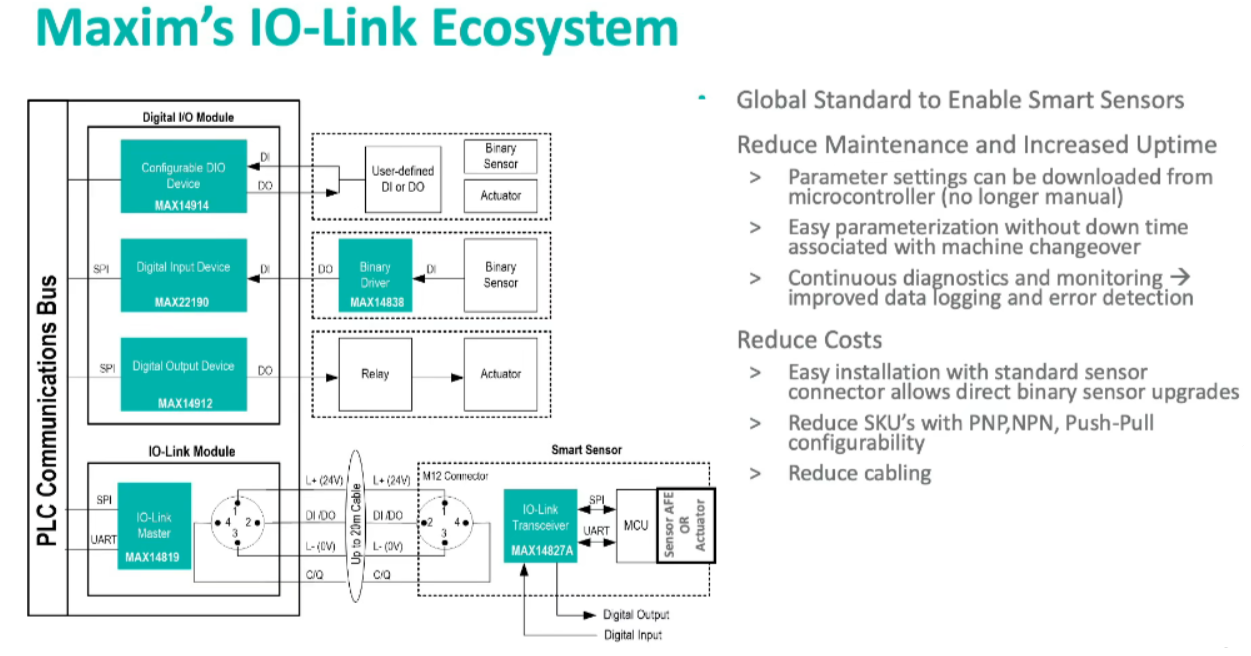
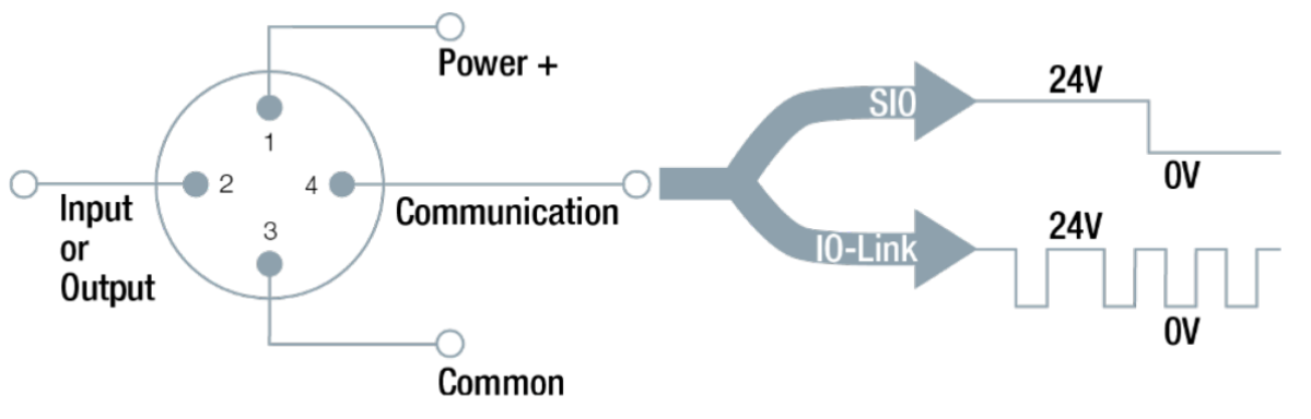
IO-Link master and slave devices communicate via physical wiring. Master and slave devices are physically connected through cables, including power lines, data lines, and signal lines. Traditional IO sensor/actuator signals are periodically collected by the master device in standard 10 (SI0) mode. As shown in the figure above, Pins 1-4 are the physical wiring pins between 10-Link devices.
The functions of each pin are as follows:
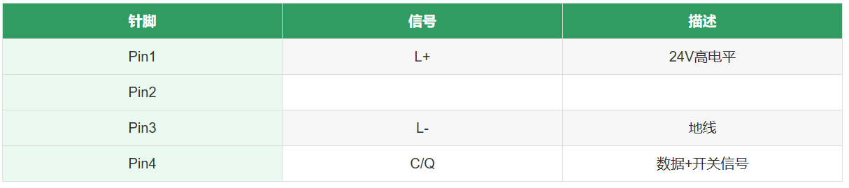
Data is transmitted via the Pin4 pin using a 24V pulse-modulated serial UART protocol. The transmitted data types include process data, parameters, diagnostics, and other service data.
In fact, these data types are similar to those transmitted in CANopen. Here, process data and service data correspond to PDO and SDO in CANopen.
The communication rate between IO-Link devices depends on the connected IO-Link devices and operates in three modes:
- 4.8 kBaud (COM1)
- 38.4 kBaud (COM2)
- 230.4 kBaud (COM3)
The data types for IO-Link are shown in the table below:
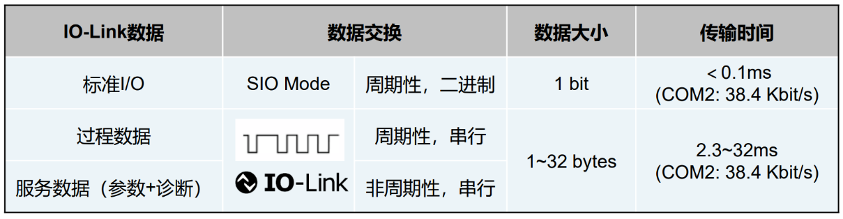
Process Data: The most common data type, used to transmit actual physical quantities measured by sensors, such as temperature, pressure, flow rate, and other measurements. Process data is typically employed in monitoring and control applications;
Service Data:
Configuration Data Packets: Used to set and configure parameters for 10-Link devices, such as sampling rate, operating mode, thresholds, etc. Devices can send configuration packets to modify their behavior and functionality.
Diagnostic Data Packets: Used to transmit diagnostic information about devices, including error codes, warning messages, fault statuses, etc. These packets assist systems in fault diagnosis and maintenance.
Identification Packets:Transmit unique device identifiers, production information, etc. (to prevent counterfeit goods circulation). This data aids system identification and management of distinct devices.
Status Packets:Convey device operational status, runtime (for technical support time logging), alarm information, status changes, and related details.
Device Capability Packets:Transmit device functional and characteristic information, such as supported operating modes, data formats, etc.
Standard I/O: Transmits event-triggered signals, such as events triggered when a device reaches a certain state or condition.
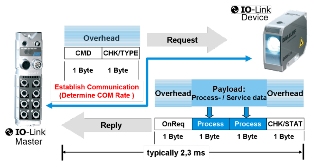
The diagram above illustrates the data transmission process between an IO-Link master and IO-Link slave devices. It demonstrates the advantages of IO-Link over traditional sensors in data transfer. The emergence of IO-Link technology enables sensors not only to collect data and upload it to higher-level systems but also allows higher-level systems to send data to sensors or actuators. Additionally, the data transmission process is extremely fast, typically taking only 2-3 milliseconds.
IO-Link Device Development and Testing
IO-Link Device Development
Application Definition:
1. Actuator or sensor functionality
2. Define cyclic data (process data)
3. IO-Link device functions (parameters, events, system commands, data storage)
MCU Selection:
- COM2: Recommended 8-bit processor
- COM3: Recommended 16-bit, e.g., Cortex-M0 or higher
Typical Performance Parameters:
- 6-15 MHz
- Flash: ±16 kByte
- RAM: ±0.5 kByte
- Current consumption: <10 mA
PHY Chip Selection:.
Two typical PHY chips.
Basic functions.
Automatic Wake-Up Request (WURQ) Detection.
RX, TX CIQ.
TX enable.
All communication speeds, Hi-side, Low-side, Push-Pull output.
Integrated frame processing.
SPI, I2C
.UART
.Additional Features
.LDO, DC/DC converter
.Temperature sensor
.Reverse polarity protection
.RC oscillator / PLL as crystal replacement
.Switching modes: NPN, PNP, Push-Pull...
.Hot swap, Line protection...
PS: What is a PHY chip?
A PHY chip, short for Physical Layer chip, refers to an integrated circuit used in computer networks to handle physical layer communications. The physical layer is a layer within the computer network architecture responsible for managing the physical transmission of data and electrical signal conversion. It transforms logical data into a signal format suitable for transmission over the network. PHY chips are typically used to connect computers, servers, routers, switches, and other network devices, enabling the physical transmission of data between links.
PHY chips are applied across various network protocols, with common examples including:
• Ethernet PHY chips: Used for Ethernet communication, converting data frames into appropriate electrical signals for transmission over Ethernet.
• USB PHY chips: Employed in USB (Universal Serial Bus) interfaces, handling data transfer and electrical signal conversion for USB devices.
• PCIe PHY chips: Used for PCI Express interfaces, handling high-speed data transmission between PCIe devices..
• Wireless communication PHY chips: In wireless communications like WiFi, Bluetooth, and mobile networks, PHY chips convert data into wireless signals and vice versa..
• Fiber optic communication PHY chips: Used for fiber optic communication, converting data into optical signals for transmission through fiber.
Consistency Testing:
Why Perform Conformity Testing?
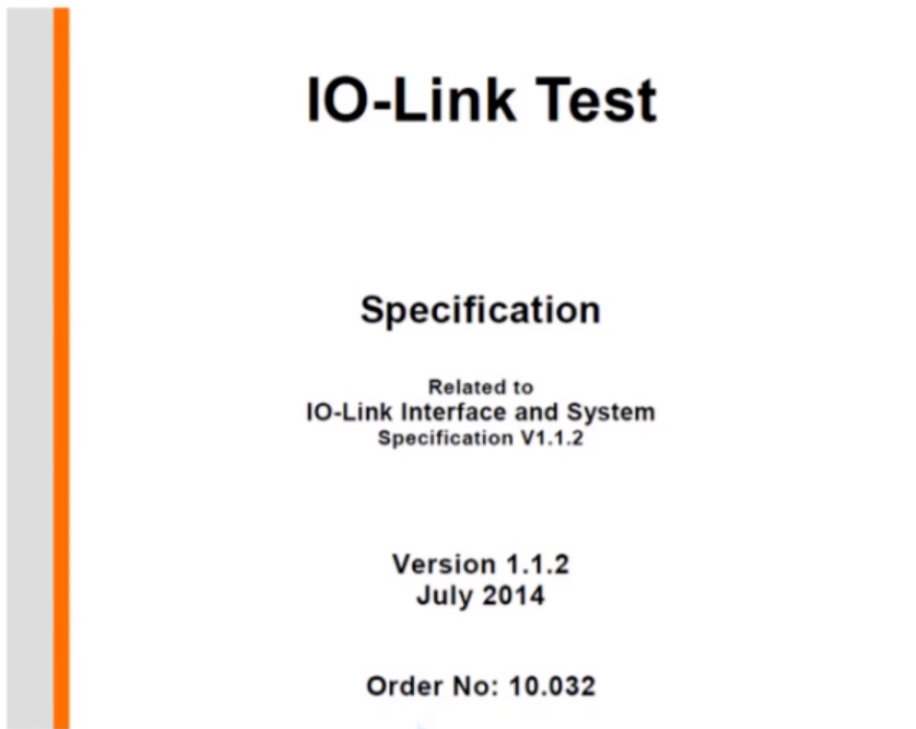
Conformity testing verifies whether devices, systems, or applications are correctly implemented and operate according to the IO-Link standard.
Conformity testing must be conducted prior to publishing an MD.
The IO-Link Quality Working Group is responsible for drafting and maintaining the documentation.
The document details the technical specifications for master and device testing.
It includes specifications for test equipment information.
Document access: IO-Link official website
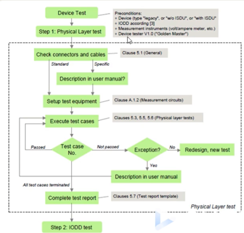
Test Items
• Physical layer test: Requires electronic equipment and is typically performed manually
• Protocol test: Must be conducted using a protocol test system approved by the IO-Link Technical Committee
• EMC test: EMC testing is specified in the IO-Link interface specification and requires dedicated electromagnetic compatibility test equipment
Consistency Testing Process
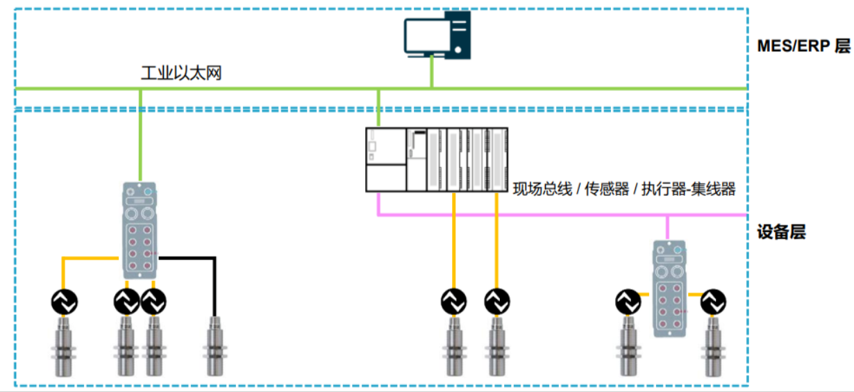
IO-Link Configuration on Different Buses
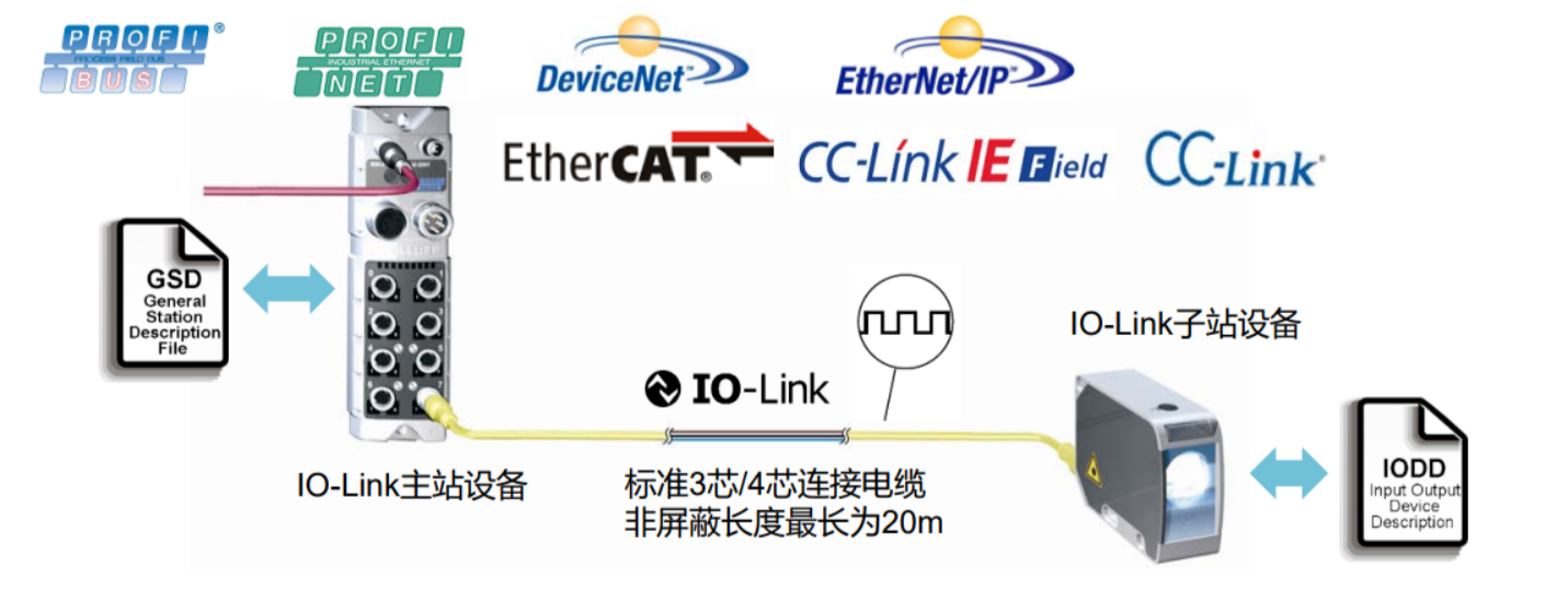
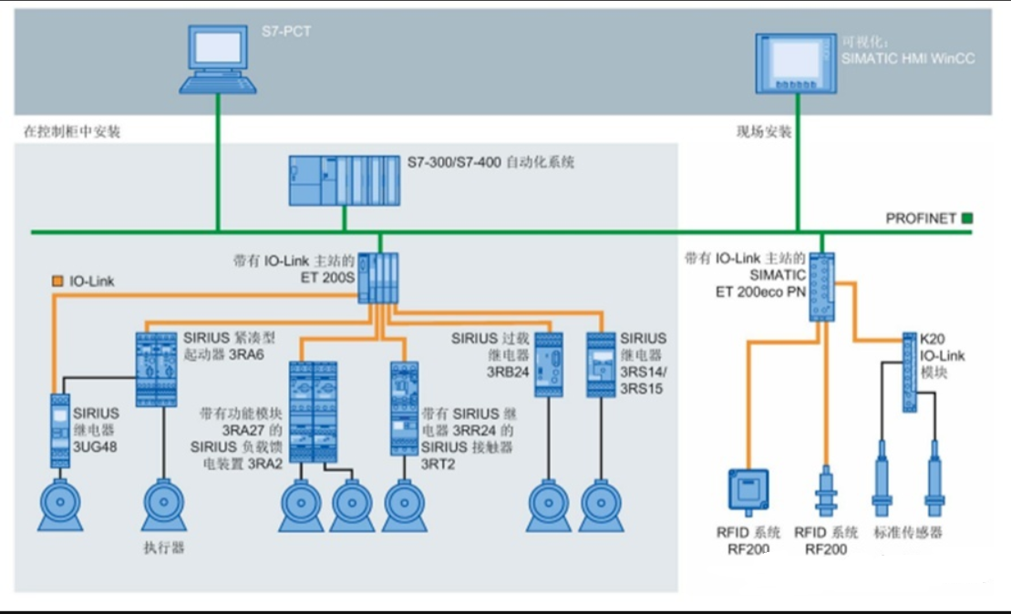
The Relationship Between IO-Link and Bus Systems
As shown in the diagram above, 10-Link does not impact the system bus. On the contrary, 10-Link bridges the "last mile" between controllers and sensors/actuators. It does not compete with the bus but rather enhances system integration and standardization.
. 10-Link does not rely on existing bus technologies and can be integrated into them.
Uses standard M12 and M8 connectors with 3-pin and 5-pin cables.
Unified interface capable of transmitting D1, DO, analog signals, etc.
IO-Link Configuration Summary.
IO-Link is compatible with mainstream bus protocols.
IO-Link system components are simple, easy to assemble, and have low communication cable requirements.
Configuration is similar across different buses; communication is achieved based on the required input/output process data size of the slave.
IO-Link communication diagnostics are easy to implement!.
IO-Link communication easily acquires various device data, facilitating maintenance and monitoring
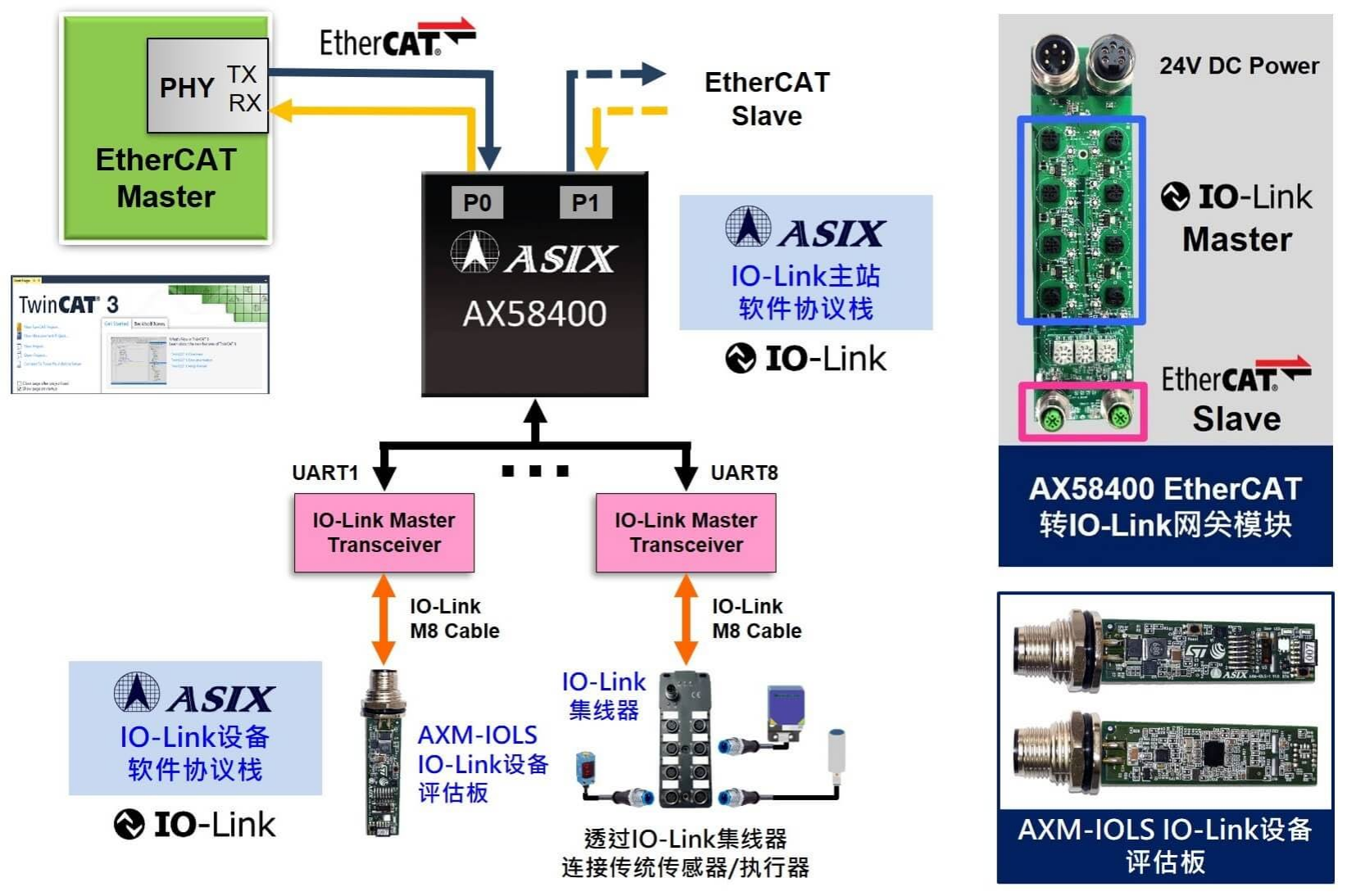
IO-Link Device Software Protocol Stack
The AsiaInfo IO-Link Device Software Protocol Stack is designed based on the AsiaInfo Electronics AXM-IOLS IO-Link Device Evaluation Board, featuring the STMicroelectronics STM32F469AI microcontroller and developed within the STM32Cube IDE development environment. This software stack suite includes the trial library for the AsiaInfo IO-Link Device Software Protocol Stack, IO-Link sensor drivers, and demonstration applications. The software architecture of the AsiaInfo IO-Link Device Software Protocol Stack is built upon STMicroelectronics' STEVAL-BFA001V2 software development kit, integrating AsiaInfo's independently developed IO-Link device software protocol stack library. Customers using the AXM-IOLS IO-Link Device Evaluation Board can conduct full-featured testing and evaluation of the AXM IO-Link Device Software Protocol Stack Trial Library within the 72-hour trial period after activation, excluding firmware upgrade functionality.
Features
• Compliant with IO-Link Interface and System Specification V1.1.3
• Backward compatible with IO-Link V1.0 masters
• Source code conforms to ANSI-C 99 standard
• Supports firmware updates via IO-Link interface
• Operating modes: IO-Link mode and standard I/O mode
• Supports ISDU communication and data storage
• Achieves consistent process data exchange (PDE) via alternating buffers
• Supports all telegram types and baud rates: 4.8Kbps (COM1), 38.4Kbps (COM2), and 230.4Kbps (COM3)
• Minimal footprint: RAM < 1KB, Flash < 10KB
• Developed based on the AXM-IOLS IO-Link Device Evaluation Board featuring the ST L6362A IO-Link transc
Product Applications
IO-Link Sensors
Temperature/Humidity/Pressure/Photoelectric/Vision/ToF Gesture Sensors, etc.
IO-Link Actuators
Valve Actuators/Motor Control/Smart LED Beacons, etc.
IO-Link Hubs
IO-Link Valve Islands