





Industrial electronic equipment operates in electrically noisy and mechanically challenging environments. The problem is that automation, control and instrumentation components depend on accurate signals free of electrical interference or distortion to function properly. As a result, optocoupler modules are often used by engineers as signal sources and as signal protection intermediaries between power supplies, industrial controls and other components.
In industrial applications, an optocoupler module is a self-contained DIN-rail mounted device that provides optical isolation of the signal path. At its core is an optocoupler, a circuit with a light-emitting diode or LED and a photosensitive device. The input side of the optocoupler module consists of the power or signal input electronics and the LED. the output consists of the photosensitive device (usually a phototransistor or photodiode) in the output circuit. When current is passed through the LED, it causes the emission of infrared light, which activates the photosensitive device, thereby allowing current to pass through the output of the optocoupler. In this way, the optocoupler output is analogous to a digital switch that turns on and off depending on the presence of an input voltage signal.
A key parameter of an optocoupler is the current transfer ratio or CTR, which is a measure of the ratio between the input and output currents. While industrial controllers can operate without an optocoupler, the latter improves safety, reliability and accuracy, and avoids the potential problems of making direct (non-isolated) signal connections.
1. Optocoupler modules protect against electrical interference: From simple mechanical limit switch signals to protocol-based data transmission, everything in an industrial environment is susceptible to electrical noise. These signals are most vulnerable if they have to travel any distance. Here, optocouplers isolate the common mode noise generated by stray currents flowing through the ground connection. To do this, properly set up the system using the optocoupler by connecting the source and receiver circuits to separate ground and signal connections.
2. the optocoupler module connects the high-voltage and low-voltage circuits: They can be damaged if the signal input to the industrial controller exceeds the set limits ...... However, it is often necessary to keep track of power levels. For example, a PLC's digital input may be designed to accept 24 Vdc, but needs to monitor a 220 V AC load. Connecting 220 Vac directly to the PLC input will obviously damage the latter. Therefore, an optocoupler module may accept a 220 Vac input and generate a feedback output voltage within the maximum allowable input range of the controller.
3. Optocoupler modules protect industrial controllers from transient events: Transients are sudden short-lived bursts of voltage or current. Despite their short duration, transients can cause significant damage to industrial controllers. Here, an optocoupler module can be used as an isolation barrier between the industrial controller and any field sensors that are exposed to surges or inrush currents.
While optocoupler modules primarily isolate the input signal from the power supply, some designs help ensure the quality of the output signal. For example, some optocoupler modules can replace electromechanical signal relays. The latter typically operate with low switching currents of 2A or less. This makes optocouplers with similar or higher output currents well suited to replace... but are designed to last longer because there are no moving parts. More specifically, electromechanical relays typically operate for 100,000 to 1,000,000 cycles ...... but optocoupler-based relays can last for decades. In addition, optocoupler modules avoid the electromechanical problems of back electromotive force and signal bounce.
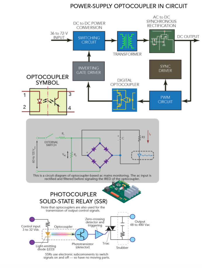
The fast switching of optocoupler-based solid state relays makes them suitable for a wide range of high-power system output loads. Optocouplers can also supplement industrial power supplies with isolation.
High-speed switching optocouplers also protect standard control and control power signals such as pulse width modulation or PWM and Modbus RS485, to name just two examples. Here coupling-based EMI coupling is minimized by isolating the controller and the receiving element.
Over-zero detection with optocoupler modules
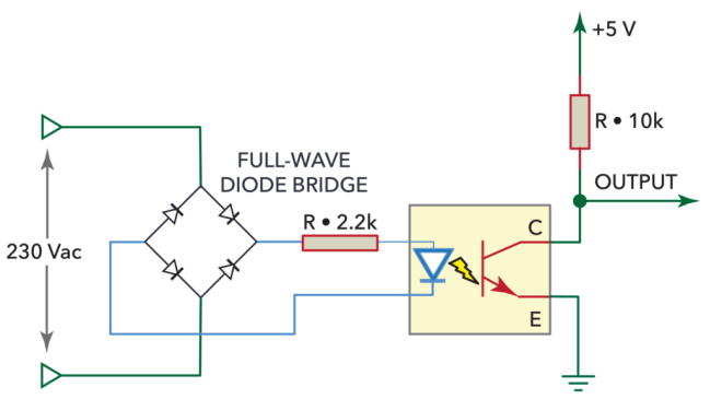
Some AC-based applications require over-zero detection, which is a measurement of the transition of an AC signal as it switches above and below zero. Here, the over-zero circuit allows the controller to measure the frequency and phase of the waveform, as well as the narrow pulse that forms at the output each time the AC signal crosses the 0 V point. Variations of the over-zero detector circuit abound, but the optocoupler-based detector circuit is superior. The optocoupler provides a noise isolation barrier between the AC signal and the controller... Many optocoupler modules even have built-in zero detection circuits to minimize device count.
When an optocoupler supplements the power supply, it typically isolates the system DC/AC, AC/AC, AC/DC, or DC/DC converter in the feedback control loop of the power supply (along with the input side transformer). This arrangement eliminates all direct conductive paths between the power input and all output terminals (and any connected field devices, motors, or other loads) for a safer, more efficient design. On equipment that regularly switches between very different power states, optocouplers can (even up to tens of kV/μsec) protect the power supply from transient common-mode voltages. In high-voltage applications, optocouplers can also disconnect ground loop currents caused by different power supplies and are designed to have a small difference in ground potential, thus eliminating common-mode electrical noise problems.
How to choose an optocoupler module
These are the primary parameters that determine the most appropriate optocoupler module selection.
Input Voltage - Determine the maximum voltage of the input signal and select an optocoupler module above the limit.
Output Voltage and Current - Ensure that the output of the optocoupler can handle the voltage and current required by the application. Some optocoupler modules have high current or high voltage output ratings.
Response Time - Any optocoupler used for high-speed signaling needs a response time in microseconds (μsec).
Mounting - Optocoupler circuits can be built from scratch, but DIN-rail mounting modules are easy to install.