





Output imbalance in variable frequency drives is a common issue in industrial automation, potentially leading to abnormal motor operation, equipment damage, or even production accidents. This article will thoroughly analyze the causes of output imbalance in variable frequency drives and propose corresponding solutions to help engineers and technicians effectively address this challenge.
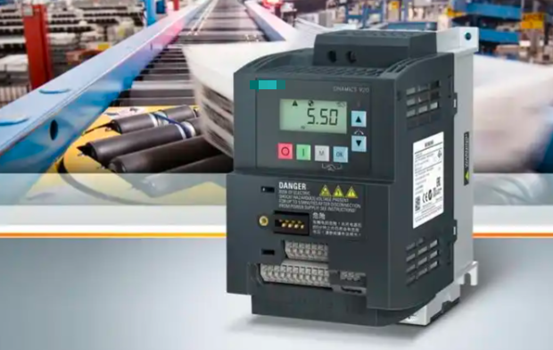
I. Manifestations and Hazards of Output Imbalance in Frequency Converters
Output imbalance in frequency converters primarily manifests as inconsistent voltage or current amplitudes across three phases, along with phase asymmetry. Specific symptoms include:
1. Motor vibration during operation and abnormal noise increase.
2. Excessive motor temperature rise, accelerating insulation aging.
3. Significant torque pulsation, affecting equipment operational stability.
4. Frequent fault codes such as overcurrent or overload from the VFD.
5. Increased energy loss and reduced system efficiency.
Prolonged operation under unbalanced conditions not only shortens the service life of motors and VFDs but may also lead to more severe safety incidents. Therefore, timely diagnosis and resolution of output imbalance issues are critical.
II. Primary Causes of VFD Output Imbalance
Based on technical analysis and engineering practice, VFD output imbalance is typically caused by the following factors:
1. Power Supply Side Issues:
● Grid voltage imbalance (exceeding the 2% limit specified by national standards).
● Power phase loss or poor contact.
● Transformer winding faults.
● Uneven load distribution in the power distribution system.
2. Internal Inverter Faults:
● Aging or damaged IGBT power modules.
● Abnormalities in drive circuits.
● Degraded capacitance of DC bus capacitors.
● Control board detection circuit failures.
● PWM modulation algorithm anomalies.
3. Output-Side Issues:
● Localized short circuits or grounding in motor windings.
● Leakage currents due to damaged cable insulation.
● Loose or oxidized terminal connections.
● Output filter failure.
4. Improper parameter settings:
● Unreasonable carrier frequency configuration.
● Mismatched V/F curve parameters.
● Incorrect motor parameter identification.
● Insufficient dead-time compensation.
III. Methods for Diagnosing Inverter Output Imbalance
1. Electrical Measurement Method:
● Measure three-phase output voltage using a true RMS multimeter; deviation should be <1%.
● Detect three-phase output current with a clamp-on ammeter; imbalance should be <10%.
● Observe PWM waveform symmetry via an oscilloscope.
2. Software Monitoring Method:
● Read internal current detection values from the VFD.
● Analyze fault history records.
● Check power module temperature parameters.
3. Mechanical Inspection Method:
● Inspect motor bearings for binding.
● Verify coupling alignment.
● Test load mechanical balance.
4. Insulation Testing Method:
● Measure motor winding insulation resistance to ground using a megohmmeter.
● Inspect cable insulation resistance.
IV. Solutions for Inverter Output Imbalance
(I) Power Supply Side Improvement Measures
1. Install a three-phase voltage stabilizer to ensure input voltage imbalance <2%.
2. Install an input reactor upstream of the VFD (typically select 2-4% voltage drop).
3. Adjust load balancing within the power distribution system.
4. Regularly inspect the status of contactors and circuit breakers in the distribution panel.
(II) VFD Maintenance and Adjustment
1. Power Module Maintenance:
● Regularly test IGBT conduction voltage drop (Vce).
● Replace aged capacitors (typically required every 5-8 years).
● Clean heat sinks to ensure adequate thermal dissipation.
2. Parameter Optimization:
● Re-execute motor parameter self-learning.
● Adjust dead-time compensation parameters.
● Optimize carrier frequency (typically set to 2-8kHz).
● Configure appropriate V/F curve (increase low-frequency torque compensation for heavy loads).
3. Control Strategy Upgrade:
● Replace V/F control with vector control.
● Enable output current closed-loop control.
● Configure harmonic suppression function.
(III) Output-Side Processing Solutions
1. Motor System Maintenance:
● Measure DC resistance of motor three-phase windings using an LCR meter (deviation <1%).
● Perform motor turn-to-turn insulation testing.
● Inspect bearing condition and replace if necessary.
2. Cable Management:
● Replace cables with aged insulation.
● Shorten cable length (generally ≤100 meters).
● Employ symmetrical cabling.
3. Install Output Filters:
● Install dv/dt filters.
● Use sine wave filters (particularly suitable for long cable applications).
● Configure common-mode chokes.
(IV) Advanced Solutions
1. Adopt three-level topology inverters to significantly improve output waveform quality.
2. Utilize Active Front-End (AFE) rectification technology to reduce grid-side interference.
3. Deploy predictive maintenance systems for real-time monitoring of critical parameters.
4. Apply artificial intelligence algorithms for fault prediction and parameter self-tuning.
V. Preventive Maintenance Strategy
1. Establish a regular inspection system:
● Measure three-phase voltage/current balance monthly.
● Inspect insulation status quarterly.
● Conduct comprehensive power module testing annually.
2. Operational data logging and analysis:
● Record historical fault information.
● Create trend analysis charts.
● Set early warning thresholds.
3. Spare Parts Management:
● Stock critical wear parts (e.g., capacitors, driver boards).
● Establish a spare parts replacement schedule.
4. Personnel Training:
● Conduct regular technical training sessions.
● Compile equipment operation and maintenance manuals.
● Develop emergency response plans for fault handling.
VI. Case Study Analysis
A 37kW pump VFD system at a chemical plant experienced output imbalance, manifested as:
● Phase U current exceeded phases V and W by 15%.
● Motor temperature rise reached 80K (normal <60K).
● Frequent VFD overload fault reports.
Troubleshooting Process:
1. Grid voltage inspection revealed a 5% deficiency in Phase U voltage.
2. Examination identified severe oxidation at the Phase U terminal in the distribution cabinet.
3. After cleaning and tightening the terminal, voltage normalized.
4. Performed motor parameter self-learning on the VFD.
5. Adjusted the carrier frequency from 6kHz to 4kHz.
6. Installed an output reactor.
Post-Treatment Results:
● Three-phase current imbalance reduced to within 3%.
● Motor temperature drop returned to normal range.
● System operating efficiency improved by 8%.
VII. Future Development Trends
1. Application of wide bandgap semiconductor (SiC/GaN) devices will significantly improve output characteristics.
2. Digital twin technology enables real-time condition monitoring and predictive maintenance.
3. Adaptive control algorithms automatically compensate for unbalanced states.
4. Integrated design reduces intermediate components, lowering imbalance risks.
Output imbalance in variable frequency drives requires systematic analysis and resolution. Through scientific diagnostic methods, appropriate solutions, and standardized preventive maintenance, this issue can be effectively addressed to ensure safe and stable equipment operation. While technological advancements will enhance output balance in new-generation drives, foundational maintenance and management practices remain indispensable. Enterprises are advised to establish comprehensive equipment management systems and cultivate specialized technical personnel to fundamentally guarantee the reliable operation of production systems.