





RS-485 Overview
Like RS-232, RS-485 is a serial communication standard. Its current official designation is TIA-485/EIA-485-A, but it is commonly referred to as the RS-485 standard. RS-485 is widely used in industries such as industrial automation, automotive, and building management.
The RS-485 bus overcomes the shortcomings of RS-232, such as short communication distances and low data rates. RS-485 supports data rates of up to 10 Mbit/s and has a theoretical communication distance of up to 1,200 meters. Unlike the single-ended transmission of RS-232, RS-485 uses differential transmission via a pair of twisted-pair wires, with one wire designated as A and the other as B.
RS-485 Physical Layer
The RS-485 physical layer is responsible for transmitting raw data between devices and the physical transmission medium. It handles the conversion of electrical signals to digital data, while also defining voltage levels, timing, data rates, and other parameters.
① Differential Signals
Long-distance cabling results in signal attenuation and increases the likelihood of noise and interference. This manifests as changes in voltage amplitude on cables A and B. However, the advantage of using differential lines is that subtracting the difference between the two signals cancels out the interference, allowing a normal signal to be output. The ability of a differential receiver to ignore identical voltages on both signal lines is called common-mode rejection.
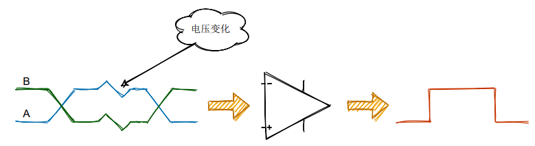

The standard specifies that logic 1 is +2V to +6V, and logic 0 is -6V to -2V.
RS-485 does not require a specific bus voltage; it only considers the minimum differential voltage. Over longer cable lengths, the voltage received by the receiver may drop to +/- 200 mV, which is still perfectly acceptable for RS-485-this is one of the advantages of RS-485.
Many transceivers meet or even exceed the TIA/EIA-485A standard; in practical applications, however, the device's specified parameters take precedence. For example, the minimum negative input threshold for a certain transceiver is -200 mV.

② Signal Definitions
Many RS-485 converters today are compatible with RS-422, so you'll often see signals labeled T/R+ and T/R- on these converters, which correspond to RS-485's A+ and B-.
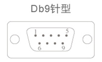
For DB9 female connectors, the RS-485 wiring definition is as follows: Pins 6 through 9 are N/A and should not be connected.
| DB9 | Output Signal | RS-422 Full-Duplex Wiring | RS-485 Half-Duplex Wiring |
| 1 | T/R+ | Send(A+) | RS-485(A+) |
| 2 | T/R- | Send(B-) | RS-485(B-) |
| 3 | RXD+ | Receive(A+) | Empty |
| 4 | RXD- | Receive(B-) | Empty |
| 5 | GND | Ground Wire | Ground Wire |
③ Topology
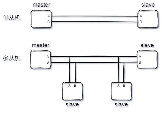
RS-485 supports both two-wire and four-wire configurations. The four-wire configuration is limited to point-to-point communication and is rarely used today; the two-wire configuration is more commonly employed. This configuration uses a bus topology, allowing up to 32 nodes to be connected on a single bus.
Like I²C, the RS-485 bus operates in a master-slave mode. It supports both point-to-point single-slave mode and multi-slave mode, but does not support multi-master mode.
RS-485 Transceiver
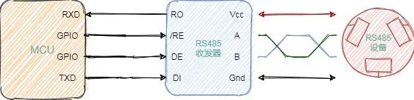
RS-485 uses differential transmission. If you want to control an RS-485 device using a microcontroller, you'll need a transceiver-similar to the CAN bus. The following diagram illustrates an MCU controlling an RS-485 device.
Inside a transceiver is a receiver (upper half) and a transmitter (lower half). Below is a brief explanation of how a transceiver works to help you understand how an MCU communicates with a 485 device.
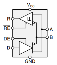
Internal Structure of an RS-485 Transceiver
Where:
A and B are the bus;
R is the receiver input;
RE is the receiver enable signal;
DE is the transmitter enable signal;
D is the transmitter output;
For enable signals, those with a line above the letter are active-low (e.g., RE in the figure above), while those without a line are active-high (e.g., DE).
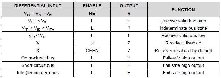
 Receiver Truth Table
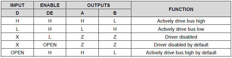
For the transmitter, the truth table is as follows:
1. When the driver enable pin DE is at a logic high, the differential outputs A and B follow the logic state at the data input D. A logic high at D causes A to go high and B to go low. In this case, the differential output voltage, defined as VOD = VA – VB, is positive. When D is low, the output states invert: B goes high and A goes low, and VOD is negative.
2. When DE is low, both outputs become high-impedance. In this case, the logic state at D is irrelevant.
The following truth table applies to the receiver:
1. When the receiver's enable pin (RE) is at a logic low, the receiver is activated. When the differential input voltage, defined as VID = VA – VB, is positive and exceeds the positive input threshold VIT+, the receiver's output R goes high. When VID is negative and below the negative input threshold VIT-, the receiver output R goes low. If VID is between VIT+ and VIT-, the output is undefined.
2. When RE is logic high or floating, the receiver output is high impedance, regardless of the magnitude or polarity of VID.

RS-485 Data Link
Having discussed the operating principles of the RS-485 transceiver above, we will now briefly describe the RS-485 data link. You may first take a look at the easy-to-understand UART protocol frame format.
Whether the master sends data to the slave or the slave sends data to the master, both the A and B lines are used; therefore, RS-485 is typically used in half-duplex mode.
The host's GPIO controls the DE pin of the RS-485 transceiver to set the transmission mode. A single byte is sent from the UART TXD line to the data (D or DI) line of the RS-485 transceiver. The transceiver converts the single-ended UART bit stream into a differential bit stream on the A and B lines. Once the data leaves the transceiver, the host immediately switches the transceiver to receive mode.
The slave operates similarly to the master. The slave controls the /RE pin of the RS-485 transceiver to set it to receive mode, receives the bit stream sent by the master, converts it to a single-ended signal, and receives it via the slave's UART RXD line. When the slave is ready to respond, it transmits data in the same manner as the master, while the master switches to receive mode.
RS-232 to RS-485 Conversion
It is possible to convert between RS-232 and RS-485. One method is to convert RS-232 to TTL, and then convert TTL to RS-485. Of course, there are also chips that support direct conversion from RS-232 to RS-485, and many such modules are available online.
RS-232 to RS-485 Conversion Modules
Differences Between RS-485 and CAN
Although RS-485 does not have a standardized data protocol format, it shares many similarities with the CAN bus. For example, both A&B and CANH&CANL are differential signals; both require transceivers for communication; and both use 120-ohm termination resistors, among other similarities.
| Bus Characteristics | CAN Bus | RS-485 Bus |
| Hardware Costs | Slightly higher | Inexpensive |
| Bus Utilization | Automatic priority arbitration, high utilization | Uses polling; low utilization |
| Data Transfer Rate | High | Low |
| Error Detection Mechanisms | The controller includes a checksum mechanism to ensure the accuracy of low-level data transmission | Only physical layer specifications; no data link layer specifications |
| Impact of a Single-Node Failure | No impact on the bus | Bus paralysis |
| Development Costs | Flexible software development, low time cost | Difficult to develop |
| System Costs | Relatively low | High |
Common RS-485 Circuits
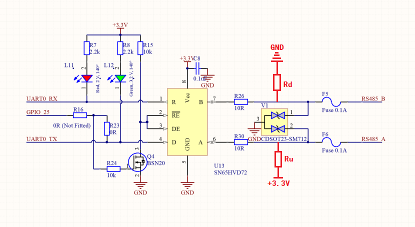
Here is a common RS-485 circuit I found online. There are two points to note:
1. The enable signals RE and DE can be controlled by a single GPIO to conserve resources. When GPIO25 outputs a high level, RE and DE are 0 V, and the device enters receive mode; when GPIO25 outputs a low level, RE and DE are 3.3 V, and the device enters transmit mode.
2. In some circuits, a pull-up resistor is added to pin A and a pull-down resistor to pin B. The main reason for this is that, when the RS-485 bus is in the idle state, the voltage level is not fixed-that is, it fluctuates between -200 mV and +200 mV-and the transceiver may output either a high or a low level. The UART must maintain a high level when idle; if the transceiver outputs a low level at this time, the UART interprets it as a start bit, which can cause communication errors. The specific values of R_u and R_d will not be discussed in detail here; I plan to write a detailed article on this topic in the future.
Regarding the second point, please note the following:
① If you apply a pull-up resistor to pin A and a pull-down resistor to pin B, data communication may fail due to reversed connections.
② If a transceiver has built-in pull-up and pull-down resistors, there is no need to add external ones.