


As an indispensable core component in modern industrial control systems, the stable operation of variable frequency drives (VFDs) directly impacts production efficiency and equipment safety. When VFD malfunctions occur, the ability to quickly and accurately pinpoint issues and implement effective countermeasures is a critical skill maintenance personnel must master. The following systematic troubleshooting methodology for common VFD faults, combining practical experience with key technical considerations, provides comprehensive guidance for fault diagnosis.
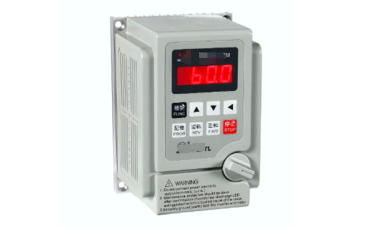
I. Visual Inspection and Preliminary Diagnosis
1. Physical Condition Check
First, inspect the VFD enclosure for deformation, burn marks, or abnormal heat. For instance, in a chemical plant case, maintenance personnel discovered severe dust accumulation in the VFD's ventilation holes, causing internal IGBT module overheating and failure. Regularly cleaning air duct dust and checking cooling fan operation (immediately replace fans with abnormal noise or stoppage) can prevent such issues.
2. Indicator Light Status Analysis
Modern inverters typically feature multi-color LED indicators. A steady green light indicates normal operation, while a flashing red light may signal an overcurrent fault (e.g., Emerson TD3000 series fault code E008). Yellow lights are often associated with communication errors. Consult the equipment manual to interpret specific code meanings. For instance, the "E.OC1" code on Mitsubishi FR-A800 series indicates an overcurrent detected during acceleration.
II. Electrical Parameter Measurement
1. Input Side Inspection
Use a multimeter to measure the three-phase input voltage. Deviations should not exceed ±10% of the rated value. A textile factory case study revealed that grid voltage fluctuations causing phase L1 loss triggered the inverter's "Input Phase Loss" fault (Siemens G120 series code F3003). It is recommended to use a true RMS meter and simultaneously check the circuit breaker contact impedance (normally <50mΩ).
2. DC Bus Inspection
With power disconnected (after 5 minutes of discharge), use a megohmmeter to test the insulation resistance between positive/negative bus bars and ground (standard value >5MΩ). In a cement plant vertical mill motor failure case, bus-to-ground resistance measured only 0.8MΩ, ultimately revealing aged insulation in the braking resistor module. After power-up, check bus voltage; for 380V models, the normal range should be 510-540VDC.
3. Output Side Diagnostics
Use a clamp-on ammeter to measure three-phase output balance. Deviations >10% may indicate IGBT damage. In one case, abnormally high U-phase current occurred during pump operation, confirmed by detection as an open circuit in the lower bridge arm IGBT of phase U. It is recommended to observe the PWM waveform using an oscilloscope; a normal waveform should be a regular square wave.
III. Key Component Specific Testing
1. Capacitor Inspection
Failed electrolytic capacitors are a common fault source. Measure capacitance with a capacitance meter (replace if decay exceeds 20%), while also inspecting for bulging on the capacitor top. At a steel mill, a VFD frequently reported "DC under-voltage"; inspection revealed the filter capacitor's ESR value had risen from the rated 0.5Ω to 3.2Ω.
2. IGBT Module Testing
Test using diode mode:
● Forward and reverse resistance between Gate (G) and Emitter (E) must be >100kΩ.
● Forward voltage drop between Collector (C) and Emitter (E) should be 0.3-0.7V.
In an injection molding machine case, a short circuit was detected between CE terminals of an IGBT unit. The fault was resolved after replacement.
3. Circuit Board Inspection
Key inspection points:
● Input/output characteristics of driver circuit optocouplers (e.g., PC929).
● Zero-point drift of current sensors (Hall effect sensors).
● Presence of burn marks on PCB copper foil.
Use a magnifying glass to check for cold solder joints. In one case, pulse loss occurred due to cracked solder joints on the driver board.
IV. Software and Parameter Verification
1. Parameter Backup and Comparison
During sudden failures, first export current parameters for comparison with backups. One production line's inverter was mistakenly set with excessively high "torque boost" values, causing motor overheating. Normal operation resumed after restoring factory defaults. Pay special attention to whether motor nameplate data (power/voltage/current) is accurately entered.
2. Fault Record Analysis
Retrieve the inverter's historical fault records (e.g., ABB ACS880 stores up to 50 entries) to analyze operating conditions during fault occurrence. In a centrifuge case, records revealed multiple "overload" alarms occurred during acceleration phases, ultimately confirming mechanical transmission jamming.
3. Application of Software Diagnostic Tools
Employ manufacturer-specific software (e.g., Danfoss DriveWindow) for online monitoring to observe real-time curves of critical parameters like temperature and current. In one instance, software analysis revealed improper carrier frequency settings causing high-frequency vibration.
V. Environmental and Load Inspection
1. Environmental Adaptability Assessment
Inspect installation environment:
● Temperature (ideal range: -10°C to +40°C).
● Humidity (<90% without condensation).
● Vibration (<0.5G).
A coastal factory experienced control board short circuits due to salt spray corrosion, necessitating enhanced protection ratings.
2. Load Characteristic Verification
Check:
● Motor insulation resistance (>1MΩ).
● Mechanical transmission system resistance torque.
● Load inertia ratio settings.
In a crane case, a wire rope jam caused an over-torque fault, resolved through mechanical adjustment.
VI. Advanced Diagnostic Techniques
1. Infrared Thermal Imaging Applications
Scan operating inverters; normal temperature differential <15℃. One case revealed a 25℃ temperature difference across rectifier bridge arms; disassembly confirmed dried thermal paste.
2. Vibration Spectrum Analysis
Detect abnormal vibrations via accelerometers. A fan VFD caused mechanical resonance due to output harmonics, resolved by adjusting the carrier frequency.
3. EMC Interference Detection
Use a spectrum analyzer to check:
● Input-side harmonic content (THD < 5%).
● Output-side dv/dt (recommended < 1000V/μs).
A PLC malfunction case originated from an inverter lacking an output reactor.
VII. Maintenance Decision Tree
Establish a tiered handling process:
Level 1 Fault (Parameter error/Operational mistake) → Immediate reset.
Level 2 Fault (Capacitor aging/Fan failure) → Scheduled maintenance.
Level 3 Fault (IGBT failure/Board burnout) → Professional repair.
A certain automotive plant reduced average fault resolution time from 8 hours to 2 hours using this process.
Conclusion
Inverter fault diagnosis should follow the principle of "from external to internal, from simple to complex," combined with the four-step method of "observing, listening, inquiring, and measuring." Enterprises are advised to establish a preventive maintenance system, including:
● Quarterly maintenance (dust removal/fastening).
● Annual inspections (capacitors/insulation).
● Triennial overhauls (replacement of aged components).
Systematic inspection methods and scientific maintenance strategies significantly enhance VFD operational reliability. Practice demonstrates that standardized maintenance reduces VFD failure rates by over 60% and extends average service life by 3-5 years. Maintenance personnel should continuously update their knowledge base, particularly regarding testing techniques for new SiC power devices, to keep pace with technological advancements.