





As a critical component in modern industrial control systems, the frequency adjustment of variable frequency drives (VFDs) directly impacts motor speed and production efficiency. This article provides a systematic overview of the principles, methods, precautions, and typical application scenarios for VFD frequency adjustment, helping readers gain a comprehensive understanding of this key technology.
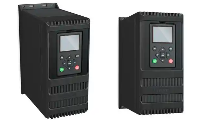
I. Fundamental Principles of Frequency Adjustment in Variable Frequency Drives
Variable frequency drives control the speed of AC motors by altering the frequency of the output power supply. Their core principle is AC-DC-AC conversion technology: first rectifying utility-frequency AC power into DC, then converting it back into AC with adjustable frequency via an inverter. When the output frequency drops from 50Hz to 30Hz, the motor's synchronous speed correspondingly decreases by 40%, enabling stepless speed regulation.
Key technical parameters include:
1. Fundamental Frequency: Typically 50Hz/60Hz, corresponding to the motor's rated speed.
2. Frequency Range: General-purpose inverters typically operate from 0.1 to 400Hz.
3. Resolution: Modern inverters achieve accuracy down to 0.01Hz.
II. Six Common Frequency Adjustment Methods
1. Direct Setting via Control Panel
A standard adjustment method for all VFDs, implemented through panel buttons:
● Rotary knob: Adjust via rotary encoder (e.g., ABB ACS550).
● Keypad: Step adjustment using ▲/▼ keys (e.g., Mitsubishi FR-D700).
● Touchscreen: Directly input target frequency value.
Operation flow: Enter frequency setting mode → Clear original value → Input new frequency → Confirm and save. A cement plant fan retrofit case study demonstrated that operators adjusted the frequency from 45Hz to 38Hz via the panel, achieving annual energy savings of 120,000 kWh.
2. Analog Signal Control
The most common remote control method in industrial settings:
● Voltage signal: 0-10V corresponds to 0-50Hz (Siemens MM440).
● Current signal: 4-20mA corresponds to 0-100Hz (Yaskawa GA700).
● Wiring note: Shielded cable must be used, with a maximum distance of 50 meters.
A chemical plant's PID control system uses a 4-20mA signal to adjust pump frequency in real time, improving flow control accuracy to ±1.5%.
3. Multi-Speed Preset Function
Fixed frequency switching achieved via terminal combinations:
● Typical configuration: 8-speed presets (binary encoding).
● Application scenarios: Spindle speed variation in textile machinery, elevator operating curves.
● Parameter setup: Pre-configure parameters P1000-P1015 (using Siemens as example).
An automotive production line employs 3-speed control for conveyor belts, enabling differentiated transport speeds for various vehicle models.
4. Communication Bus Control
The preferred solution for modern intelligent control:
● Supported Protocols: Modbus RTU (Delta VFD-EL), Profibus (ABB ACS880).
● Transmission Rate: Up to 12Mbps (EtherCAT).
● Topology: Supports networks with up to 128 nodes.
A smart factory utilizes PROFINET for centralized frequency management of 200 VFDs, achieving response times <10ms.
5. PID Closed-Loop Regulation
Advanced application in automatic control systems:
● Feedback Signals: Pressure/flow/temperature sensors.
● Parameter tuning: Proportional band, integral time, derivative time.
● Typical applications: Constant-pressure water supply, central air conditioning.
A residential community in Beijing employs PID control for its water supply system, reducing pressure fluctuations from ±0.3 MPa to ±0.05 MPa.
6. Program Operation Modes
Scheduled automatic speed variation scheme:
● Programmable segments: Typically 16–64 segments.
● Time unit: Minimum 0.1 seconds.
● Application example: Mold opening/closing speed curve for injection molding machines.
III. Five Key Considerations for Frequency Adjustment
1. Motor protection: Enhanced cooling required for prolonged low-frequency operation (<10Hz).
2. Mechanical resonance: Avoid sustained operation in the 30-40Hz range (e.g., fan equipment).
3. Voltage Matching: V/F curve settings must match motor nameplate specifications.
4. Acceleration/Deceleration Time: Set 5-30 seconds for soft start/stop in high-inertia loads.
5. Electromagnetic Interference: Maintain >30cm distance between signal cables and power cables.
A steel mill suffered over 800,000 yuan in losses due to gearbox damage caused by neglecting resonance point settings.
IV. Reference Parameters for Typical Industry Applications
| Industry | Common Frequency Range | Adjustment Method | Energy-saving effect |
| Central Air Conditioning | 30-50Hz | PID closed-loop | 35-45% |
| Oilfield Pumping Unit | 20-40Hz | Programmed Speed Change | 28% |
| Paper production line | 15-55Hz | Communication Control | 22% |
| Mine Hoist | 10-45Hz | Multi-speed | 18% |
V. Cutting-Edge Technology Developments
1. AI Self-Tuning: Schneider Electric's ATV930 features load characteristic learning capabilities.
2. Wireless Control: Danfoss FC302 supports Wi-Fi frequency adjustment.
3. Digital Twin: Virtual commissioning simulates the impact of frequency changes.
A smart manufacturing demonstration workshop adopted digital twin technology, reducing VFD debugging time by 70%.
Mastering VFD frequency adjustment technology not only enhances equipment control precision but also achieves significant energy savings. Users are advised to select appropriate adjustment methods based on specific operating conditions and regularly inspect parameter settings to ensure safe and efficient system operation. With the advancement of the Industrial Internet of Things, VFD frequency adjustment is rapidly evolving toward intelligent and networked solutions.