


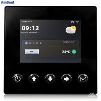


In the field of industrial automation, variable frequency drives (VFDs) serve as core equipment for motor control, where operational convenience directly impacts production efficiency. This article provides a detailed analysis of the standardized procedures for manually starting and stopping VFDs via their control panels, common troubleshooting solutions, and safety operating protocols. It aims to help technicians quickly master this fundamental yet critical skill.
I. Fundamentals of VFD Panel Operation
Modern VFDs typically feature LCD displays and physical buttons. Taking the Emerson TD900 series as an example, the panel includes Run (RUN), Stop (STOP), Mode Switch (MODE), a frequency adjustment knob, and a Function Confirmation button (ENTER). While button layouts may vary slightly across brands like Siemens G120 or Mitsubishi FR-D700, core functional key logic remains consistent. Before operation, verify three points: power voltage matching (380V/220V), pre-set motor power parameters, and control mode selection set to "Panel Operation" (configured via parameter P0-01 or similar code).
II. Detailed Standardized Startup Procedure
1. Power-On Initialization
After powering on, the panel displays the initial interface, typically showing the frequency setpoint (e.g., 0.00Hz), operating status (STOP), and fault code (displays 0 when no faults exist). The Schneider ATV312 VFD performs a 3-second self-test during this phase; no operations are permitted at this time.
2. Frequency Preset Phase
Set the target frequency using the rotary encoder or ▲/▼ keys. For conveyor belt control, initial testing at 10Hz is recommended. Yaskawa GA700 series supports quick setup: press and hold ▲ for 3 seconds to jump directly to 50Hz.
3. Execute Start Operation
Press and hold the RUN key for over 1 second (ABB ACS550 requires 2 seconds to prevent accidental activation). Observe the following changes:
● Status indicator changes from flashing to steady illumination.
● Output current value begins dynamic display.
● Actual frequency gradually rises to the set value.
Key detail: The Fuji FRENIC-Mini series displays "ACC" during acceleration at startup. If the set frequency is not reached within the acceleration time defined by parameter P08, it may indicate an overload condition.
III. Three Safety Stop Modes
1. Conventional Stop
Pressing the STOP key causes the motor to decelerate smoothly according to the deceleration time set in parameter P09 (typically 5-20 seconds). Suitable for inertial loads like fans and pumps.
2. Free-Wheeling Stop
Simultaneously pressing STOP + MODE keys (Delta VFD-EL series) immediately cuts output, allowing the motor to coast via inertia. Used in emergencies but may trigger an electrical braking alarm.
3. DC Braking
Activated via preset parameter P52, injects DC current during stopping for rapid braking. Note: Continuous use requires >15-minute intervals to prevent brake resistor overheating.
IV. Typical Fault Handling Solutions
1. Start Failure Code E.OC1
During overcurrent alarm, inspect:
● Motor insulation resistance (>1MΩ).
● V/F curve settings (select square torque characteristic for heavy loads).
● Acceleration/deceleration time (increase P08/P09 values).
2. Sudden Shutdown During Operation
Troubleshooting Focus:
● Input voltage fluctuation (tolerance range ±10%).
● Cooling fan status (Omron 3G3MX2 requires periodic dust removal).
● Parameter P50 temperature protection threshold (recommended ≤65°C).
V. Advanced Function Applications
1. Multi-Speed Preset
Configure 8 speed segments via parameters P24-P31 (using Invt GD300 as example), utilizing multifunction terminals to meet textile machinery speed variation requirements.
2. PID Closed-Loop Control
Enable P130=1 to display real-time feedback values (e.g., pressure sensor signals) on the panel. Note: Set proportional band and integral time via P131-P134.
VI. Safety Standards and Maintenance Guidelines
1. Before operation, perform the three-step verification: "Power On → Parameter Verification → No-Load Test."
2. Clean heat dissipation channels monthly using compressed air to maintain unobstructed airflow.
3. Export backup parameters via the panel's "Parameter Copy" function (Mitsubishi supports USB storage).
4. Never plug or unplug control terminal wires during operation, as this may damage the IGBT module.
A cement plant case study demonstrates that correctly using the panel's jog function (JOG key) for equipment commissioning reduces mechanical impact failures by 60%. It is recommended to verify rotation direction using jog mode during initial startup. Holding the JOG key for 3 seconds will cause the motor to run at 5Hz.
As VFDs become increasingly intelligent, new-generation equipment like Siemens SINAMICS G120X now supports touchscreen gesture controls. However, physical buttons remain the most reliable emergency control method. Mastering panel operation is not only a fundamental skill but also a critical safeguard for handling unexpected situations. Conduct quarterly hands-on drills for panel functions to ensure key operations become muscle memory.