

PROFIBUS Overview
(1) PROFIBUS is an international, open, and vendor-independent fieldbus standard. It is widely applicable in manufacturing automation, process industry automation, and automation in other sectors such as buildings, transportation, and power.
(2) PROFIBUS comprises three compatible components: PROFIBUS-DP (Decentralized Periphery), PROFIBUS-PA (Process Automation), and PROFIBUS-FMS (Fieldbus Message Specification).
(3) PROFIBUS-DP: A high-speed, low-cost communication protocol for device-level control systems and distributed I/O communication. PROFIBUS-DP replaces conventional 24VDC or 4-20mA signal transmission.
(4) PROFIBUS-PA: Specifically designed for process automation, enabling sensors and actuators to be connected on a single bus with intrinsic safety specifications.
(5) PROFIBUS-FMS: Used for shop-floor monitoring networks, it is a token-based, real-time multi-master network.
(6) PROFIBUS is a fieldbus technology for shop-floor monitoring and data communication/control at the field device level in factory automation. It enables distributed digital control and field communication networks from the field device level to shop-floor monitoring, providing a viable solution for achieving comprehensive factory automation and intelligent field devices.
Basic Characteristics of PROFIBUS
PROFIBUS Protocol Structure
The PROFIBUS protocol structure is based on the ISO 7498 international standard, using the Open System Interconnection (OSI) model as its reference framework. This model comprises seven layers, as illustrated below:
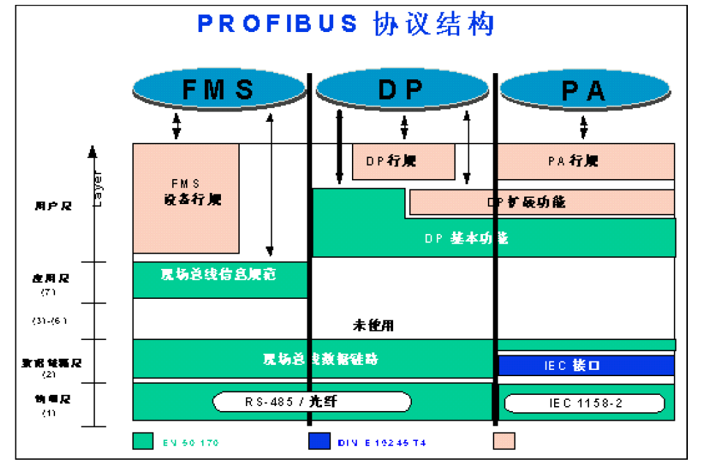
(1) PROFIBUS-DP: Defines the first, second, and user interfaces. Layers three through seven are not described. The user interface specifies application functions accessible to users, systems, and various devices, and details the device behavior of different PROFIBUS-DP devices.
(2) PROFIBUS-FMS: Defines Layers 1, 2, and 7. The application layer includes the Fieldbus Message Specification (FMS) and the Lower Layer Interface (LLI). FMS incorporates application protocols and provides users with a robust, widely selectable range of communication services. LLI coordinates different communication relationships and offers a device-independent Layer 2 access interface.
(3) PROFIBUS-PA: PA data transmission utilizes an extended PROFIBUS-DP protocol. Additionally, PA describes the PA conventions governing field device behavior. Based on the IEC 1158-2 standard, PA's transmission technology ensures intrinsic safety and enables power supply to field devices via the bus. PA networks can be extended over DP using connectors.
PROFIBUS Transmission Technology
PROFIBUS offers three data transmission types:
RS485 transmission for DP and FMS.
IEC 1158-2 transmission for PA.
Fiber Optics
RS485 Transmission Technology for DP/FMS
Since DP and FMS systems utilize the same transmission technology and unified bus access protocol, both systems can operate simultaneously on the same cable. RS-485 transmission is the most commonly used transmission technology for PROFIBUS. This technology is typically referred to as H2. Shielded twisted-pair copper cable is used.
Basic Characteristics of RS-485 Transmission Technology:
Network Topology: Linear bus with active bus termination resistors at both ends.
Transmission Rate: 9.6K bit/s to 12M bit/s
Medium: Shielded twisted-pair cable; shielding may be omitted depending on environmental conditions (EMC).
Number of Stations: 32 stations per segment (without repeaters), up to 127 stations (with repeaters).
Connector: 9-pin D-sub connector is recommended.
Key Installation Points for RS-485 Transmission Equipment
(1) All devices must be connected to the bus.
(2) Each segment can support up to 32 stations (master or slave).
(3) Each segment requires one bus termination resistor at both the head and tail to ensure error-free operation. Both termination resistors must always be powered.
(4) When a segment exceeds 32 stations, repeaters must be used to connect bus segments. Generally, no more than three repeaters should be connected in series.

PROFIBUS-DP and PROFIBUS-FMS Cable Wiring and Bus Termination Resistors
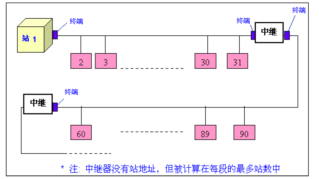
Each segment can connect up to 32 stations (master or slave).
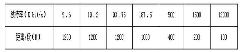
(5) The maximum cable length depends on the transmission rate. When using Type A cable, the transmission rate and length correspond as shown in the table below: