





The PROFIBUS-DP (Distributed Peripherals) fieldbus standard has existed for over two decades, yet its physical layer requirements remain unclear, frequently leading to confusion in transceiver definitions. However, any ambiguity has clearly not prevented PROFIBUS from becoming a highly successful fieldbus solution, with over 50 million devices installed worldwide. As new systems are deployed, it is crucial for design engineers to know that the transceivers they use are designed for the latest and most accurate interpretation of the PROFIBUS-DP standard.
PROFIBUS-DP (Distributed Peripherals) Fundamentals
The faster, simpler PROFIBUS-DP standard emerged in 1993 from its slower, more complex parent standard, PROFIBUS FMS (Fieldbus Message Specification). PROFIBUS-DP also has a younger, less popular peer or derivative standard, PROFIBUS-PA (Process Automation), which uses Manchester Bus Power (MBP) transmission and is powered over the bus, making it ideal for intrinsically safe applications in hazardous environments. However, PROFIBUS-DP remains the most widely used PROFIBUS version today due to its plug-and-play characteristics, flexibility, and cost-effectiveness. From managing sensors and actuators in industrial plants to communicating with flow meters in railway yards and various robotic applications, PROFIBUS-DP decentralizes I/O cards (masters) from controllers to locations closer to sensors and actuators (slaves).
PROFIBUS-DP can communicate over multiple media, including copper wire, fiber optics, and even air in infrared communicators. To date, the most common bit transmission medium (Layer 1 of the ISO/OSI model) for PROFIBUS-DP masters and slaves is twisted-pair cable using RS485 transceivers. This is unsurprising given RS485's high-speed differential signaling and robust communication over long distances between multiple devices in noisy environments. Multiple masters, such as PLCs (Programmable Logic Controllers), can connect up to 30 slaves per segment in a linear topology. Using hubs (parallel segments) or repeaters (serial segments) can extend the network to 124 slaves. Segments must be terminated at both ends using active termination. All slaves can be hot-plugged into the bus,
95% RS485, 5% confusion
PROFIBUS-DP adopts most of the TIA/EIA-485-A RS485 standard but incorporates modifications that may be inadvertently overlooked due to larger system concerns. Therefore, contrary to common belief, not all RS485 transceivers and cables are suitable for PROFIBUS-DP networks. Differences exist in wiring, termination, signal naming, and driver requirements; overlooking these too quickly can easily compromise the performance (or worse, certification) of your master or slave devices.
While the RS485 standard does not specify wiring requirements, 120-Ω shielded twisted pair (STP) cable has become the conventional recommendation. However, PROFIBUS-DP recommends 150-Ω STP cable. Unfortunately, 120 Ω cannot be approximated to 150 Ω, and this slight difference in cable impedance actually necessitates the use of different cables. PROFIBUS-DP also specifies maximum cable lengths, which depend on which of the 10 baud rate "steps" is used, ranging from 1,200 m at 9.6 kbits/s to 100 m at 12 Mbits/s.
Of course, different cable impedance requirements lead to different termination requirements. To minimize signal reflections, RS485 installations typically use a single 120-Ω terminating resistor at each end of the bus, while PROFIBUS-DP recommends a 171-Ω terminating network at each end. Wait, is that a typo? PROFIBUS-DP recommends 171 Ω, so doesn't that mismatch the 150-Ω characteristic impedance of the recommended cable? Absolutely. Figure 1 illustrates the differences between the cable and termination network used for PROFIBUS-DP versus RS485. You can see two 390-Ω bus bias resistors used with 220-Ω terminating resistors; the differential resistance is 171 Ω. This is clearly not a perfect match for 150-Ω cable, resulting in slightly insufficient network damping. But don't worry, because this indicates only a small bump or increase in the signal voltage at the cable receiving end, lasting twice the cable propagation delay.
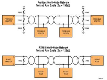 Figure 1: Differences in cables, terminations, and pin assignments between RS485 and PROFIBUS-DP networks.
If cable/termination mismatches weren't enough, the naming of bus pins on PROFIBUS transceivers should further confound your expectations. You may have noticed the reversed pin names used in Figure 1. In most generic RS485 transceivers, pin A is the common-mode receiver input (and common-mode driver output), while pin B is the differential-mode receiver output and driver input. However, the PROFIBUS standard describes bus polarity in such a way that pins B and A are reversed. Why the inconsistency? The original TIA/EIA-485-A standard did not explicitly define bus polarity in relation to logical signal function, so RS485 IC designers almost invariably interpreted the specification one way, while others interpreted it another. What does this mean for you? Especially if you have both RS485 and PROFIBUS-DP projects, you must pay close attention when mapping transceiver bus pins to connectors.
Given the number of existing transceivers with undefined specifications, the differential driver output voltage (V_(OD)) is likely the most misunderstood or overlooked specification in the PROFIBUS-DP physical layer. RS485 specifies V_(OD) between lines A and B as 1.5 to 5 V peak-to-peak differential, measured at the driver terminals using 54-Ω resistors between A and B. PROFIBUS-DP specifies V_(OD) as 4 to 7 V peak-to-peak differential, measured at the far end of the cable with terminators on both ends.
A common misconception is that if an RS485 driver produces over 2.1 V on a 54-Ω load, it will meet PROFIBUS-DP requirements when used with a PROFIBUS-DP terminated network. However, this is not always true. The RS485 driver's strength may be excessive and exceed the 7-V peak-to-peak PROFIBUS-DP limit. Note that all common "PROFIBUS"-compatible RS485 transceivers specify only a minimum V_(OD) (i.e., 2.1 V) without a maximum. The best method to ensure PROFIBUS-DP V_(OD) compliance is to test the transceiver using a PROFIBUS load.
Figure 2 illustrates how to test the LTC2877 rugged PROFIBUS RS485 transceiver using a PROFIBUS-DP load and some series resistors to simulate cable loss, where V_(OD) (blue curve) is measured from the "cable end" (A' and B') to ensure true compliance with the PROFIBUS-DP specification. The LTC2877 is also fully tested with RS485 loads to ensure VOD compliance with both standards.
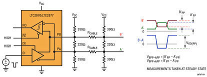 Figure 2: Testing the LTC2877 differential output voltage (VOD) using a PROFIBUS-DP load.
Protecting PROFIBUS-DP
The TIA/EIA-485-A standard provides minimal requirements for protection against noise, faults, ESD, transients (electrical fast transients), or surges. Consequently, transceiver manufacturers and designers must implement electrical protection independently. While protection requirements vary by application, certain transceivers-including the LTC2877 shown in Figure 3-deliver high-level protection that meets all market demands.
The TIE/EIA-485-A standard specifies that the ground offset between two devices on the network can range from –7 to +12 V. However, many PROFIBUS-DP installations may encounter voltages significantly higher than this, which can cause severe damage to PROFIBUS-DP transceivers. PROFIBUS is commonly used in 24V systems, where shorting a "standard" RS485 device to 24V can be fatal. Designers should require a receiver with an extended common-mode range of –25 to +25 V. Replacing typical PROFIBUS-DP transceivers with the ±60V-protected LTC2877 eliminates field failures due to overvoltage faults without requiring costly external protection. Since PROFIBUS-DP transceivers are effectively the system's first line of defense, they must protect themselves against various levels of ESD surges. Some PROFIBUS transceivers offer 15kV ESD protection on their bus pins when de-energized; other products, such as the LTC2877, provide ±26kV HBM ESD protection relative to ground or either power supply without latching or damage, whether de-energized or energized, and in any operating mode. Additionally, the bus pins are protected against ±52kV ground-to-ground surges when unpowered.
Another form of electrical overstress is EFT, defined by the IEC 61000-4-4 EFT standard as high-voltage spike pulses lasting 60 microseconds. This type of overstress is typically caused by arcing contacts in switches and relays, common in industrial environments where electromechanical switches connect and disconnect inductive loads. They should ensure the selected transceiver meets the highest level of IEC 61000-4-4, Level 4, equivalent to 2 kV open-circuit voltage on the bus pins.
Perhaps the most severe form of electrical overload is the surge delivered by nature in the form of lightning. Therefore, it is unsurprising that miniature transceiver ICs like the LTC2877 lack inherent protection against surges of this magnitude. Instead, external surge protection components, including MOVs, TVS diodes, TSPDs (Thyristor Surge Protective Devices), and GDTs (Gas Discharge Tubes), are typically used in PROFIBUS-DP systems where components are exposed in any way. The LTC2877 cannot withstand lightning strikes alone, but its high ±60V pin rating makes it easy to find external protection components capable of providing this level of protection.