





CAN bus (Controller Area Network) is a serial communication protocol widely used in automotive, industrial automation, and other fields. Below are several common CAN bus communication protocols:
1. CAN 2.0A: Also known as Standard CAN (Classical CAN), it is the most common CAN bus communication protocol. It uses an 11-bit identifier (ID) field and supports a maximum transmission rate of 1 Mbps.
2. CAN 2.0B: Similar to CAN 2.0A but employs a 29-bit identifier (ID) field, providing greater ID encoding capacity. It supports a maximum transmission rate of 1 Mbps.
3. CAN FD (Flexible Data Rate): An enhanced version of the CAN bus protocol, CAN FD delivers higher data transmission rates and larger packet capacities. It supports transmission speeds up to 8 Mbps and enables larger packet sizes.
4. CANopen: CANopen is an open high-level communication protocol designed for communication between control devices. It defines a set of communication and network management objects for data exchange and configuration between devices.
5. J1939: J1939 is a communication protocol for heavy-duty commercial vehicles and construction machinery based on the CAN bus. It defines a set of standard parameters and message formats for data exchange between vehicle electronic systems.
These represent only a small portion of CAN bus communication protocols. Additional protocols exist that are customized for specific application domains or particular manufacturers.
CAN Interface Protection and Working Principle
1. Recommended Circuit
Figure 1 shows the recommended protection circuit for the CAN interface. Proper protection significantly enhances the interface's immunity to interference. Bus interface protection is implemented in three stages: Stage 1 provides high-energy discharge, Stage 2 performs current limiting, and Stage 3 implements voltage clamping. Each stage circuit fulfills its specific function, working together to achieve optimal protection.
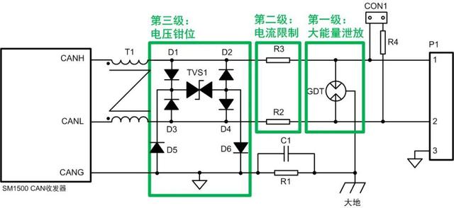 Figure 1 Recommended Protection Circuit for CAN Interface
2. Working Principle-Differential Mode Loop
As shown in Figure 2, when differential-mode interference voltage is applied to pins 1 and 2 of the interface, TVS1 responds fastest and conducts first, clamping the voltage between the chip bus pins CANH and CANL. Resistors R2 and R3 limit the current flowing through TVS1, preventing overpower damage. The GDT responds slowest and conducts last, dissipating most of the energy and limiting the residual voltage to a low level.
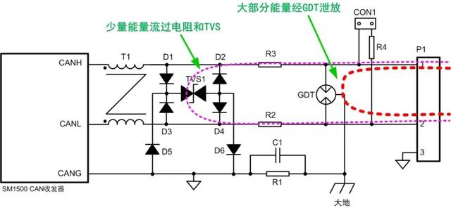 Figure 2 Differential Mode Discharge Circuit Diagram
3. Working Principle-Common-Mode Loop
As shown in Figure 3, to ensure effective protection, the communication reference ground CANG should be grounded at a single point after network configuration. When common-mode interference voltage is applied to pins 1 and 2 of the interface, TVS1 responds fastest and conducts first, clamping the voltage between the chip bus pins and CANG. Resistors R2 and R3 limit the current flowing through TVS1 to prevent overpower damage. GDT responds slowest and conducts last, dissipating most of the energy and limiting the residual voltage to a low level.
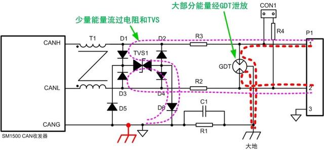 Figure 3 Schematic of Common-Mode Discharge Pathway
How to Troubleshoot Communication Circuit Failures
When encountering communication circuit failures, try the following steps to resolve the issue:
1. Check physical connections: Ensure all cables are securely plugged in and firmly connected. Verify that power cords, network cables, telephone lines, etc., are properly connected.
2. Restart devices: Sometimes, simply restarting devices can resolve communication issues. Try rebooting relevant equipment, including routers, switches, modems, etc.
3. Verify device settings: Confirm that device configuration parameters are correctly set. Review IP address, subnet mask, gateway, DNS settings, and compare them with information provided by your network service provider.
4. Eliminate interference from other devices: Temporarily disconnect other devices that may cause interference, such as radios, microwaves, Bluetooth devices, etc.
5. Update firmware and drivers: Visit the official websites of relevant devices to download and install the latest firmware and drivers, ensuring proper functionality.
6. Reset devices: For routers, switches, and similar equipment, attempt to restore them to factory settings before reconfiguring.
7. Contact your internet service provider: If none of the above methods resolve the issue, it may be due to an ISP outage. Contact them promptly to report the problem.
8. Seek professional assistance: If you are unfamiliar with circuit repairs or network troubleshooting, it is advisable to seek help from a qualified technician who can diagnose and resolve the issue more accurately.