





Selecting the optimal industrial automation equipment such as motors, drives, and communication modules requires careful attention to detail. For instance, the North American National Electrical Manufacturers Association (NEMA) and the European International Electrotechnical Commission (IEC) exhibit numerous differences in motor and drive ratings.
Factors to consider when selecting motors, drives, and controllers include input and output voltages and tolerances, required speed ranges and regulation needs, torque requirements, acceleration, braking duty cycles, special demands like fast or torque response, and environmental factors including thermal management.
Communication requirements vary based on a device's position within the industrial control hierarchy. At the layer closest to the factory shop floor edge, protocols like IO-Link can be used for smart sensors and actuators, while EtherCAT, PROFINET, Modbus, and other protocols connect motion, safety, I/O, and vision systems.
The highest layer of factory automation networks typically employs Ethernet/IP to connect diverse automation controllers, programming interfaces, and the cloud, alongside protocols like DisplayPort for human-machine interfaces (HMIs). Between these layers, a combination of Ethernet/IP, EtherCAT, and other protocols connects the field level of the shop floor to the operational and control layers.
The details are too numerous to cover comprehensively in a single discussion. Instead, this article presents several guidelines to consider when specifying motors, drives, and communication modules, along with application, hardware, and protocol examples from [Siemens], [Phoenix Contact], [Omron Automation], Panasonic [Industrial], and [Schneider Electric].
Shifting Focus
Motors and drives are common elements across many industrial automation systems. As a starting point for this discussion, it is helpful to understand where motor efficiency fits within broader considerations of industrial automation system performance and how the focus has shifted.
Using more efficient motors can save up to 6% in energy. That's good. However, adding high-efficiency drives and supporting components can save up to 30% in energy.
When the focus shifts to holistic system optimization, true game-changers emerge. By considering all mechanical components and adding communication to integrate with the Industrial Internet of Things (IIoT)-spanning operational and plant levels, ultimately reaching enterprise and cloud levels-savings of up to 60% in energy consumption and higher energy productivity can be achieved (Figure 1).
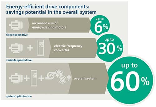 Figure 1: Enhanced integration and communication levels can save more energy and boost productivity. (Image source: Siemens)
Eco-design of Motor Systems
IEC 61800-9 Part 2, "Eco-design of Motor Systems - Energy Efficiency Determination and Classification," can serve as a key resource. It does not focus solely on motor efficiency but details a series of higher-level performance factors for "motor drive systems." VFDs are considered complete drive modules (CDMs), comprising an AC input "feed section," a "basic drive module" (BDM) like the VFD itself, and "auxiliary equipment" including input/output filters, line chokes, and other supporting components.
The standard further defines a Power Drive System (PDS) as a CDM plus a motor. Subsequently, it describes a motor system as a PDS plus motor control equipment such as contactors.
The highest level is the extended product, or the overall system in Figure 1, which adds mechanical drive equipment like gearboxes and load machines. For a more detailed understanding of the IEC 61800-9-2 PDS efficiency standard, see the article "[What Are the Different Types of Variable Speed Industrial Motor Drives?]".
The starting point for specifying a "motor drive system" is the motor itself.
Motor Considerations
When properly specified and used, motors can be highly efficient machines. This makes motor selection a critical task for machine designers.
IEC quantifies motor power in kilowatts (kW), while NEMA uses horsepower (hp), making direct equivalence straightforward. However, IEC and NEMA employ different efficiency calculations; for identical motor designs, IEC nameplate efficiency may slightly exceed NEMA ratings.
Actual motor efficiency is closely tied to specific applications. Consequently, motor efficiency standards are typically discussed in terms of reduced energy losses rather than absolute efficiency values.
IEC 60034-30-1 recognizes five motor efficiency classes, ranging from IE1 to IE5. Energy losses decrease by 20% between successive classes. This means an IE5 "Ultra Premium" motor exhibits 20% lower losses than an IE4 "Super Premium" motor. Additional factors warrant consideration. In certain scenarios, higher-efficiency motors may exhibit reduced power factor (PF).
In North America, NEMA's energy efficiency ratings are less common but equally important. NEMA recognizes the Motor Service Factor (SF), which is not included in IEC standards. A NEMA motor with an SF of 1.15 can operate continuously at 115% of its rated capacity, although this results in higher motor operating temperatures, leading to reduced bearing and insulation life.
IEC identifies ten operating types or service factors (S1 to S10) based on considerations such as continuous versus intermittent operation, speed variation, and brake usage, rather than SF.
NEMA and IEC differ in their voltage and frequency ranges, but both are expressed in "per unit" (pu) quantities. In the pu system, quantities are represented as fractions of a base value. NEMA identifies a series of motor voltages and frequencies. IEC identifies two "zones" (Figure 2).
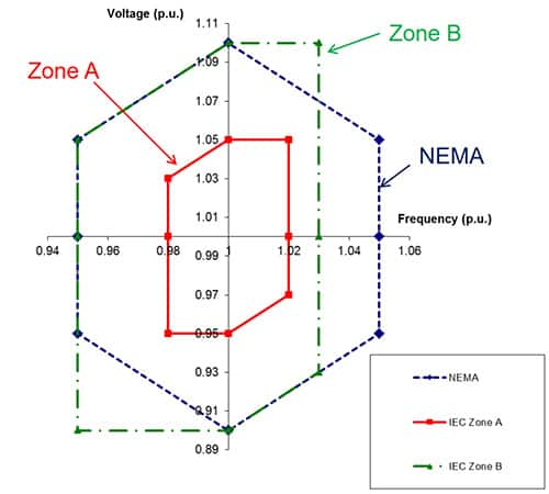 Figure 2: Comparison of NEMA and IEC Industrial AC Voltage and Frequency Ranges. (Image source: NEMA)
Enhancing PDS Efficiency
Motor drives are key components for PDS efficiency as defined in IEC 61800-9-2. They can be categorized in various ways, such as motor voltage, power level, motion type, supported applications, and more. Motion types can be classified as continuous or discontinuous. Based on the required maximum power output, they can be further divided into low-performance, medium-performance, and high-performance categories.
Different drive types support distinct system requirements. Servo drives and motors are well-suited for applications like robotics requiring rapid acceleration, deceleration, and precise positioning. Soft starters are ideal for continuous operation, such as conveyors benefiting from smooth starts and stops. VFDs are widely used across various industrial machinery.
Certain VFD product lines are optimized for operations such as pumping, ventilation, compression, mobile applications, or machining. The Siemens SINAMICS G120 series general-purpose drives are rated from 0.55 to 250 kW (0.75 to 400 hp) and are suitable for general industrial applications in the automotive, textile, and packaging industries.
Model [6SL32203YE340UF0] operates on three-phase power with an input voltage range of 380 to 480 Vac ±10% / -20%. In Europe, motors rated 22 to 30 kW are specified for 400 V operation, while in North America, motors rated 30 to 40 hp are rated for 480 V (Figure 3).
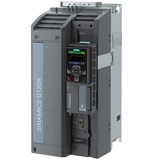 Figure 3: This VFD can be used with motors rated from 22 to 30 kW, depending on the operating voltage. (Image source: DigiKey)
VFDs are not the only key to efficient PDS design. The article "[What Supporting Products Are Needed to Maximize the Impact of Using VFDs and VSDs? - Part 1]" reviews some essential supporting components.
Communication and System Optimization
Although motors and drives reside at the first or field level of the factory floor, they are not the lowest layer in the Industry 4.0 communication hierarchy. This position belongs to Level 0 functions like sensors and actuators. Furthermore, multiple levels exist above the field level. To maximize the overall efficiency, productivity, and sustainability of an Industry 4.0 plant, timely and efficient communication from the communication hierarchy to the cloud is essential. The following protocols facilitate cloud connectivity:
- uOPC PubSub Bridge integrates multiple operational technology (OT) data streams.
- MOTT Broker receives messages and forwards them to users based on message topics.
Level 1 encompasses more than just drives and motors. Fieldbus Master Units (FMUs) facilitate communication and simplify the integration of drives and other devices. FMUs support various protocols including PROFINET, PROFIBUS, DeviceNet, CANopen, and more. Using FMUs enables manufacturer-independent connectivity.
Panasonic's [AFP7NPFNM] model is a PROFINET FMU. It features an integrated function library with programming software, significantly reducing development time for specific application solutions.
Sensors, Actuators, and Safety Level 0
To maximize PDS energy savings in VFDs, connectivity must be reduced to Level 0. Integrating sensors, actuators, and safety devices like light curtains at Level 0 significantly boosts efficiency, achieving energy savings exceeding 30%.
Common protocols for connecting Level 0 functions include DeviceNet, HART, Modbus, and IO-Link. IO-Link is a point-to-point protocol connecting sensors and actuators to higher-level controllers. Available as both wired and wireless standards, it is increasingly deployed in Industry 4.0 as a cost-effective alternative.
[Omron's NX-ILM400] IO-Link master units can mix standard I/O with high-speed synchronous I/O. Standard digital I/O offers 16 connections per unit, with options including:
- Four 3-wire sensors with power supply
- Eight 2-wire contact inputs or actuator outputs
- Sixteen 1-wire connections for sensors and actuators connected to a common power supply
PDS Level 2 and above
High-level communication enhances field operations, but it is essential for maximizing organizational efficiency and productivity. From Level 2 to Levels 3 and 4, the cloud requires protocols such as Ethernet/IP, EtherCAT, and Modbus TCP/IP.
Devices used to establish these connections include Programmable Logic Controllers (PLCs) or Industrial Personal Computers (IPCs). PLCs are computers optimized for industrial automation and control. In typical applications, a PLC monitors inputs from machines and associated sensors, makes decisions based on its programming, and sends control outputs.
While IPCs can perform PLC-like functions, they are more general-purpose devices. Running operating systems like Linux or Windows, they access a broader range of software tools and typically connect to HMIs (though many PLCs also connect to HMIs). PLCs tend to be machine-centric, whereas IPCs offer more operational capabilities.
The distinction between PLCs and IPCs is increasingly blurred. For example, Phoenix Contact's [1069208] PLC runs the Linux operating system. Like traditional PLCs, it can be programmed using Symbolic Flowchart (SFC), Ladder Diagram (LD), Function Block Diagram (FBD), and Structured Text (ST). It includes three independent Ethernet interfaces and can connect to PROFICLOUD.
Schneider Electric offers the [HMIBMIEA5DD1E01] IIoT Edge Box for applications benefiting from IPC capabilities. This fanless design incorporates a dual-core Intel Atom Apollo Lake E3930 processor operating at 1.8 GHz. It features one mini PCIe expansion slot and nine communication ports.
Conclusion
This article briefly outlines some guidelines designers should consider when specifying motors, drives, and communication modules for Industry 4.0 installations. It is far from exhaustive. Its purpose is to provide food for thought and some resources for further research.