




There are a large number of stepper motor applications in the industrial field, such as automation control, robot joints, printer control, etc. The most widely used are hybrid stepper motors. One of the most widely used is the hybrid stepper motor, which is also the form of most of the stepper motors we come into contact with on a daily basis. Conceptually, stepper motors and variable reluctance motors there are certain links and differences, this paper will initially talk about the structure and working principle of the reluctance motor / stepper motor, and compare the differences between the different motors.
1. Variable reluctance motor
Variable reluctance motor (Variable-Reluctance Machine) is also known as switching reluctance motor, perhaps the simplest of all the motor structure of the motor, by the stator equipped with excitation windings and ferromagnetic rotor with a convex pole structure. The rotor has no coil windings and no permanent magnets, and relies on the variation of the rotor's reluctance at different positions to generate an electromagnetic force (dΨ/dθ).
We know that the magnetic flux always tends to cross the path with the lowest reluctance. As shown in Fig. 1.1, S1 S2 controls the current on and off, and VD1 VD2 is the current continuity diode. The position shown in the position of AA' and aa' position of the maximum reluctance, CC 's minimum reluctance, if the D phase is energized at this time, the rotor will rotate counterclockwise; if the B phase is energized at this time, the rotor will rotate clockwise; if the A phase is energized at this time, the rotor to remain unchanged. It should be noted that switched reluctance motors cannot realize the change of motor rotation direction through the change of current direction, but through the change of energizing sequence to realize the forward and reverse rotation of the motor.
Clockwise rotation energizing sequence: B-A-D-C
Counterclockwise rotation energizing sequence: D-A-B-C
Since the motor's magnetic resistance changes drastically during rotation, the torque pulsation of the reluctance motor will become high. In order to ensure that the motor can run smoothly and efficiently, controlling the reluctance motor requires knowing the position of the rotor, the state of the load, and the state of the speed, among other information. And the model of the reluctance motor does not have the good linearity of the permanent magnet synchronous motor/asynchronous motor, so it needs a lot of prediction models and algorithms to improve the control accuracy, which undoubtedly increases the difficulty of the reluctance motor control.
 Figure 1.1 Basic structure of variable reluctance motor
2. From variable reluctance motors to stepper motors
Variable reluctance motors can subdivide the angle of movement by increasing the number of stator and rotor poles or the number of energized phases of the stator due to their special control method (pulsed alternating conduction). There are a variety of such subdivided structures with different angular torque characteristics, so they will not be discussed. In this article, we will explore several common variable reluctance motor mechanisms, from different dimensions to see how stepper motors stand out from the myriad of variable reluctance motor structures.
2.1 Castle type variable reluctance motor
As mentioned earlier, increasing the number of protruding poles can subdivide the angle of movement, but the more protruding poles will take up a lot of coil space, the motor winding efficiency is reduced, and the protruding poles can't be increased indefinitely. In the case of the same number of drive phases, by engraving a small tooth on the protruding pole, can also be subdivided by the machine distance angle. As shown in Figure 2.1, a three-phase castle-type variable reluctance motor with a 6-pole stator, 4 teeth per pole, and a 28-pole rotor. Energizing coil 1, coil 2, and coil 3 sequentially can drive the rotor to rotate with a step distance of 2β/3 at each step. β values need to be designed according to the cogging ratios of the motor design and are not discussed here.
This type of motor is generally used in low speed, high torque and precision angular resolution, this structure can already be called " stepper motor ", because the control of this motor as well as can be detached from the position detection , through the pulse sequence drive can realize a relatively smooth control.
 Figure 2.1 Three-phase castle-type variable reluctance motor
2.2 Multi-stage variable reluctance motors
Variable reluctance motors consisting of a single rotor with a multi-phase winding are also known as "single-segment variable reluctance motors". Another type of variable reluctance motor is a rotor and stator divided into many segments, which can be subdivided without increasing the number of stator phases, and is more friendly to the winding structure of the stator. It is possible to set up a segment with one phase, which virtually eliminates the interwinding end of the multiphase motor. For n-segment motors, the rotor or stator of each segment is staggered by 1/n of the angle of its pole pitch, and the pole pitch can be further subdivided by n times.
2.3 Hybrid stepper motors
In a simple variable reluctance motor, the direction of rotation depends on the timing of the pulse current and the reluctance structure of the motor, and is not affected by the direction of the current. In the absence of current, the rotor cannot be fixed in a specific position due to the lack of reluctance torque, which further increases the difficulty of control. Adding permanent magnets to the original switched reluctance motor structure to form a permanent magnet or hybrid variable reluctance motor can significantly improve the torque and positional accuracy of stepper motors, which is the most common stepper motor structure today.
As shown in Figure 2.2, the hybrid stepper motor structure is very similar to the multi-segment variable reluctance motor, inserted between the two segments of the rotor permanent magnets, can be seen in the proximal end of the N-pole distal end of the S-pole. The stator can be designed as a single-segment motor structure, and only two-phase drive is required, greatly simplifying the motor structure and cost. The number of rotor pole pairs in the motor shown in the figure is 3, so the mechanical angle corresponding to one electrical cycle is 360/(2*3) = 60.
For ease of understanding, θ is the mechanical angle, and the specific driving sequence:
θ=0~10, phase 1 and phase 2 pass positive current of equal amplitude at the same time
θ=10~20, phase 2 passes positive current alone
θ=20~30, phase 1 passes negative current alone
θ=30~40, phase 1 and phase 2 pass negative current of equal amplitude at the same time
θ=40~50, phase 2 passes negative current alone
θ=50~60, phase 1 passes positive current alone
Cyclic conduction... ...
 Figure 2.2 Hybrid stepper motor structure
3. stepper motor control
As shown in Figure 3.1, the stepper motor drive circuit structure can generally be divided into bipolar motors and unipolar motors: unipolar motors through the alternating conduction of the winding to achieve a change in the direction of the flux, bipolar motors through the control of the H-bridge to achieve a change in the direction of the current to achieve a change in the direction of the flux.
Unipolar motor only needs 4 power MOS, unipolar control of the current (from the perspective of the MOS tube), but the motor winding needs one more tap; bipolar motor is simpler in structure, two windings are highly utilized, but it needs to be increased to 8 power MOS for driving, and the cost of the controller will rise.
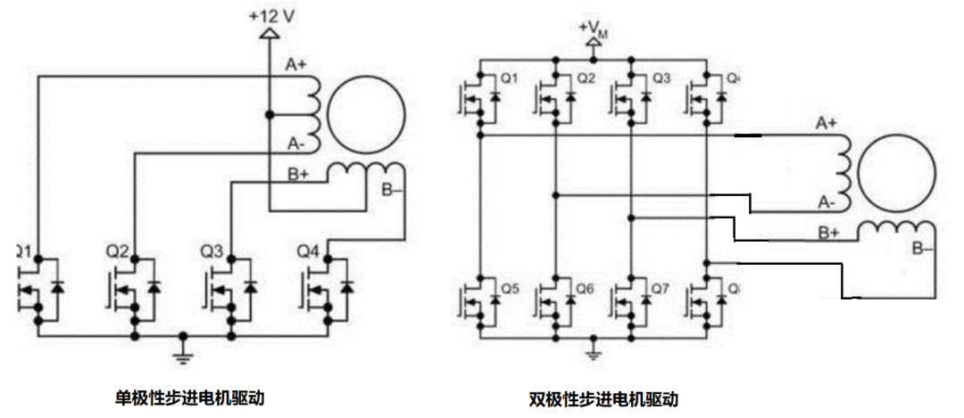 Figure 3.1 Unipolar and bipolar stepper motor drives
In addition to subdivision in the motor structure, stepper motors can also control the subdivision accuracy of the stepper motor by controlling the waveform of the current. The principle of subdivision is to insert the simulated sinusoidal current between the smallest step angles to subdivide the step angles, which is also called current subdivision.
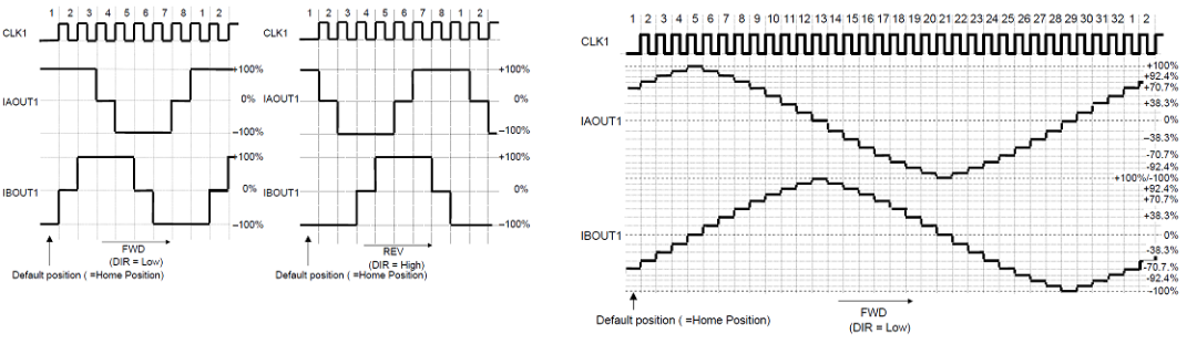 Figure 3.2 Breakdown of stepper motor drive current
3.1 Closed Loop Current
The current setting of the stepper motor needs to be determined according to the demand of the load, the larger the load, the larger the driving current needs to be, but the open-loop control of the stepper motor can't sense the size of the load, which often results in the inefficiency of the open-loop drive. Current subdivision requires precise control of the current, the need to form a closed loop of the controlled current, that is, the current output for the constant current characteristics; on the other hand, due to the nonlinear change of the magnetoresistance in the stepper motor, the need to always monitor the size of the output current to prevent the core from saturating the current caused by the loss of control. Figure 3.3 below, for the stepper motor driver chip TB67S109AFNG current control waveform schematic. Fchop for the internal switching cycle, through the internal clock (Internal OSC) frequency division.
The specific constant current control steps are as follows:
The H-bridge conducts, the current rises rapidly to NF, and the slope of the current rise is VDC/Ls
Reach the set current point NF, turn off the H-bridge, the current is renewed by the renewal diode, and the slope of the fall is -VDC/Ls (Fast change)
When the current reaches the set point lower line value, control the H-bridge to short circuit the inductor coil (generally the lower bridge), and keep the current constant (Slow change)
When the current of the set point changes, the H-bridge through the same control strategy to control the current in the latest current set point to remain constant
As shown in Figure 3.4, is the measured waveform of the stepper motor, if the subdivision of the accuracy of the lower can be seen obvious step-like current waveform ,. If the degree of subdivision is very high, then the current is closer to a sinusoidal current, as shown in Figure 3.5.
 Figure 3.3 TB67S109AFNG current control
 Figure 3.4 Measured current of stepper motor (not subdivided)
 Figure 3.5 Stepper motor measured current (subdivision)
3.2 Open-loop and closed-loop control
With open-loop control, since there is no feedback of rotor position information, it is essentially unknown whether the system is being followed by the control or not. If there is some load abnormality, it is easy to cause the stepper motor to lose steps. In some high-precision, high-performance applications, through the encoder or other position sensors back to the position information, so that the stepper drive system can be whether or not the loss of step has occurred, if the loss of step will make up for the loss of pulse in the control of the control is also relatively easy to realize.
Summary
This paper briefly describes the basic structure of variable reluctance motors and their evolution to stepper motors, and compares the structure and control logic of several common stepper motors. The stepper motor control principle and the control details of current subdivision are introduced to provide a more comprehensive understanding of stepper motors.